Apparatus for Gasifying and Separating a Liquid Medium or the Like

a technology of apparatus and liquid medium, which is applied in the direction of liquid degasification, separation process, evaporation, etc., can solve the problems of complex apparatus structure, complex mechanical mechanism of automating the addition of solvent, and the withdrawal of purified solvent, so as to achieve high accuracy and high reliability , the effect of increasing the siz

Inactive Publication Date: 2009-07-02
TECHNO SIGMA
View PDF2 Cites 12 Cited by
  • Summary
  • Abstract
  • Description
  • Claims
  • Application Information

AI Technical Summary

Benefits of technology

[0022]The apparatus of the present invention is an apparatus for gasifying and separating a liquid medium or the like, which is advantageous not only in that it can measure a varying liquid surface position of a liquid medium or the like with high accuracy, but also in that it can be increased in size. Further, the apparatus has the following advantages. A wide range of the subjects of treatment and conditions for operation can be used. The control mechanism can be automated, and hence a safety mechanism conventionally required is not needed, thus achieving high reliability and safety. In addition, the apparatus can reduce the cost.

Problems solved by technology

(2) In the conventional apparatus which is not of a circulation system, the mechanisms of automating the addition of a solvent, the withdrawal of a purified solvent, and the discharge of concentrated mother liquor for continuously operating the apparatus are complicated due to the restrictions by the structure.
(3) There are many problems to be solved, e.g., complicated structure of the apparatus and cumbersome operations.
Most of the prior art techniques for purifying a great amount of a liquid medium or the like are of a batch-wise system, and there are no productive facilities of a so-called completely automatic recovery system for liquid medium or the like in which gas to be forcibly brought into contact with a liquid medium or the like is allowed to circulate through an apparatus for recovery of a liquid medium or the like to recover and separate the medium.
However, there are problems in that the form of vaporizer is complicated and the materials usable in such processing for the vaporizer are restricted.
A level gage of an electrostatic method, an electrode method, or an ultrasonic method has a problem to be solved in the direct measurement in a concentration vessel such that sensing a liquid surface position using, for example, a change of the capacitance or conductivity or an ultrasonic waveform causes the measurement in a solid mixed solution system to be inaccurate, and hence the level gage of this type has not yet been applied to a large-sized apparatus.
In a rotating container, such as a rotary evaporator, a surface position of liquid varies, and therefore it is difficult to use a float switch.
On the other hand, a closed evaporator made of stainless steel has a disadvantage in that external light cannot pass through the liquid phase in the evaporator, and hence it is basically unsuitable for automatic sensing.
However, this method has a problem in that the form of vaporizer is complicated.
When using a photosensor (patent document 3), there is a problem in that the container must be transparent and the usable materials are restricted, making it difficult to automate the apparatus and increase the size of apparatus.
When using a CCD sensor (patent document 4), there is a problem in that image processing for the continuously varying liquid surface is complicated, making it difficult to increase the size of apparatus.
However, measurement for a varying liquid surface (for example, a surface of the liquid being stirred or mixed) by the method using a differential pressure gauge and a weight meter in combination is difficult.
Even when calibration is made using a weight meter or means of a differential pressure gauge and a weight meter and the like are used in combination, it is difficult to specify a varying liquid surface position.
In any of the above methods, a varying liquid surface position cannot be measured while maintaining a series of gasification-separation operations including charging of the liquid to be purified into a distillation apparatus, discharging of the purified liquid, and discharging of the residue in the required level or cost.

Method used


Image

  • Apparatus for Gasifying and Separating a Liquid Medium or the Like
  • Apparatus for Gasifying and Separating a Liquid Medium or the Like
  • Apparatus for Gasifying and Separating a Liquid Medium or the Like

Examples


example 1

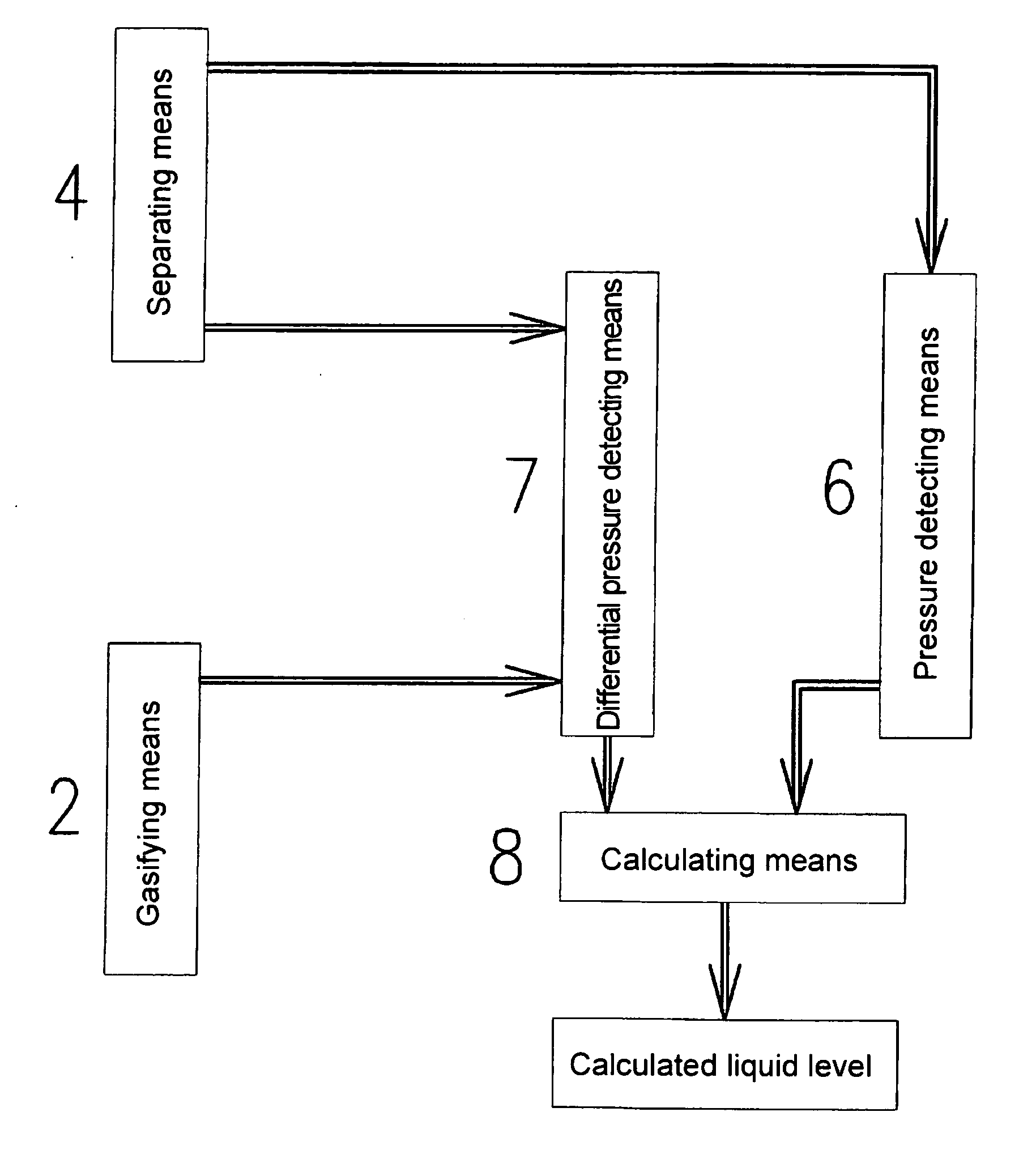
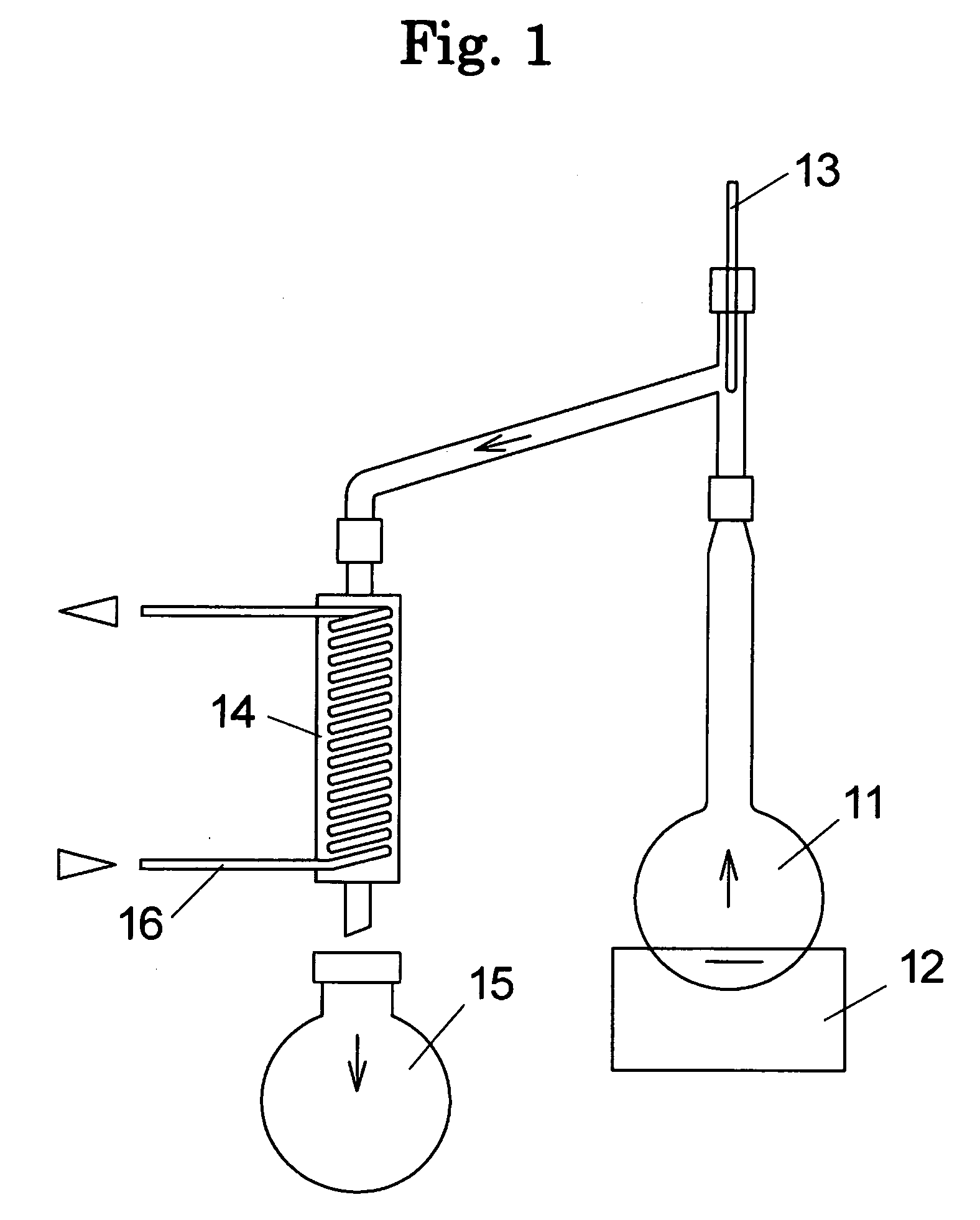
[0162]In apparatus 10 for gasifying and separating a liquid medium and a mixture of the present invention, container 110 (flask type; capacity: 10 L) was first warmed to 35° C. using a warm water bath and a coolant (−10° C.) was fed to condenser 140, and then rotation of container 110 (stirring) using a large-sized rotary evaporator for solvent evaporation was started, performing detection control for preparation of the operation.

[0163]Then, pump 200 was operated for about 5 minutes to discharge the residual volatile substance from the pump.

[0164]The apparatus (gasifying-separating apparatus 10) was evacuated to set value A-1 (−80.0 kPa) of compound gauge S2. Then, a methanol solution was charged from unpurified crude liquid tank 156.

[0165]A liquid surface position in the container was measured. Specifically, a comparison between a liquid surface position and set value B-1 (0.5 kPa) of differential pressure gauge S1 was made, and, when the liquid surface position was lower than set ...

examples 2 to 9

[0169]Substantially the same procedure as in Example 1 was conducted except that the type of the solvent to be recovered and the temperature of the heating bath were changed as shown in Table 2.

[0170]The results of Examples 1 to 9 are shown in Table 2.

TABLE 2Recovery of solvent under reduced pressureHeating bathFlow rate forFlow rate for recoveryRecovery rate ofType of organictemperaturefeed of solventof organic solventorganic solventExamplesolvent recovered(° C.)(ml / min)(ml / min)(%)1Methanol355.0120>992Methanol405.0124>993Ethanol405.083>994Methylene chloride405.0223>995Ethyl acetate405.0194>996PGMEA805.093>997Toluene805.0243>998Xylene805.0188>999Water805.068>99

Recovery of Solvent Under Atmospheric Pressure Conditions

example 10

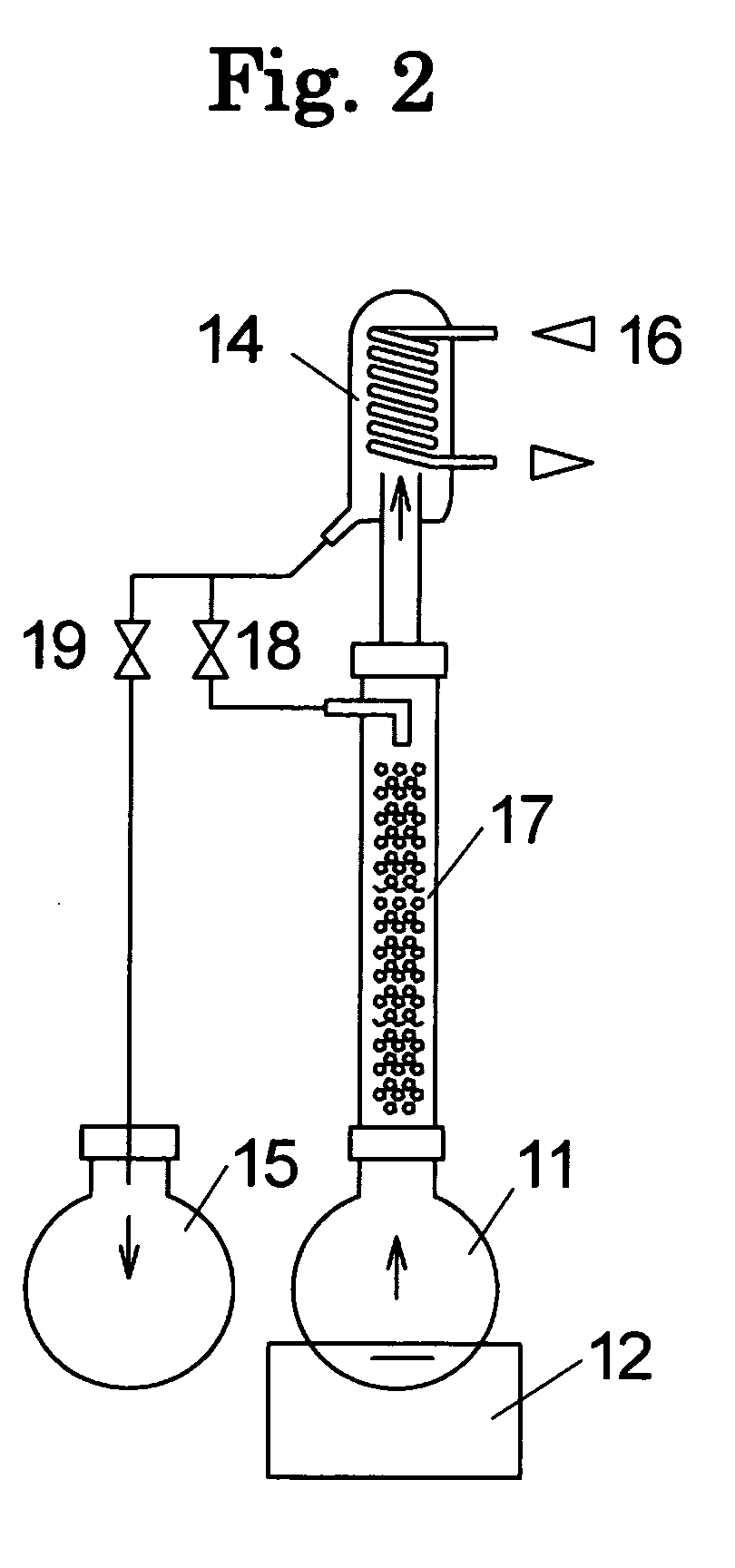
[0171]In the apparatus of the present invention, discharge of the residual volatile substance by the detection control for preparation of the operation, and the detection control for feeding of a liquid from the unpurified crude liquid tank were conducted in substantially the same manner as in Example 1 except that the temperature of the heating bath was 65° C.

[0172]Then, atmospheric gas was permitted to flow the apparatus until a value reached set value F-2 (−1.0 kPa) of the compound gauge, so that the pressure of gas became atmospheric pressure.

[0173]Subsequently, a gasification-separation control was conducted. In this control, while feeding gas to a container for gasification, a diaphragm pump was operated to keep set value C-2 (about −5 kPa) of compound gauge S2. Simultaneously, detection of a liquid surface position and recovery were conducted. A point in time when a value reached set value E-2 (0.2 kPa) of the differential pressure gauge was determined as an end point of the ...


PUM

PropertyMeasurementUnit
boiling pointaaaaaaaaaa

Abstract

To provide an apparatus for gasifying and separating a liquid medium, which is of an automatic type and which can be increased in size.An apparatus for gasifying and separating a liquid medium and a mixture, comprising a gasifying means, in which one liquid selected from a liquid medium and a mixture of the liquid medium and a nonvolatile substance is stored to form a liquid surface of the liquid, for gasifying the liquid medium to form a gasified medium, and a separating means for cooling gas and the gasified medium discharged from the gasifying means to condense the gasified medium, separating the condensed medium from the gas, the apparatus comprising: pressure detecting means for detecting a pressure of the gas; a differential pressure detecting means for detecting a differential pressure between a pressure in the gasifying means at a predetermined position and the pressure of the gas; and a calculating means for calculating the liquid surface position of the liquid from the predetermined position as abase position based on the pressure of the gas and the differential pressure to determine a calculated liquid surface position, wherein the surface position of the liquid varies due to gasification of the liquid, wherein the calculated liquid surface position is a liquid surface position corresponding to the surface position obtained when the liquid is still.

Description

FIELD OF THE INVENTION[0001]The present invention relates to an apparatus for gasifying and separating a liquid medium or the like, which is an automatic apparatus advantageous not only in that it can measure a varying surface position of a liquid medium or the like with high accuracy, but also in that it can be increased in size.BACKGROUND ART[0002]In recent years, there is increasing concern about environment problems, and, for controlling the chemical substances and others that are possibly harmful to human health and ecosystem, international standards, such as ISO, and laws, such as PRTR (Pollutant Release and Transfer Register), are prepared. For dealing with such movements, reusing the used liquid medium and others to reduce the amount of the solvent discharged has attracted attention, and, as apparatuses for this purpose, recently, a variety of separation apparatuses named, e.g., organic solvent distillation apparatus, solvent recycling apparatus, and automatic solvent recove...

Claims


Application Information

Patent Timeline
Patent Type & Authority Applications(United States)
IPC IPC(8): B01D19/00
CPCB01D1/0052B01D3/085B01D5/0063B01D3/42B01D3/14
Inventor TORII, SHIGERUMIKI, KOUICHIKORETOMO, KATSUMI
Owner TECHNO SIGMA
Why Eureka
Try Eureka