Outer blade cutting wheel and making method

a cutting wheel and outer blade technology, applied in the direction of gear teeth, gear-teeth manufacturing apparatus, other chemical processes, etc., can solve the problems of imposing an ever increasing demand, and achieve the effects of improving the mechanical nature of the bond used in the blade section, enhancing the overall mechanical strength of the outer blade cutting wheel, and excellent mechanical strength

Active Publication Date: 2009-07-02
SHIN ETSU CHEM IND CO LTD
View PDF12 Cites 29 Cited by
  • Summary
  • Abstract
  • Description
  • Claims
  • Application Information

AI Technical Summary

Benefits of technology

[0023]Specifically, the mechanical nature of the bond used in the blade section is improved to enhance the overall mechanical strength of the outer blade cutting wheel. In this way, a high-performance, high-strength cutting wheel is provided. While resin bonds of phenolic resins or the like are most commonly used in the art, they are scarcely expected to exert their own mechanical strength because of the resinous or plastic nature. According to the invention, a blade section is formed using as the bond a single metal or metal alloy having excellent mechanical strength rather than the resins or plastics, whereby the blade section is improved in mechanical properties, and at the same time, the strength of the base is reinforced. In this way, a high-performance outer blade cutting wheel with improved mechanical rigidity or ro

Problems solved by technology

However, the market imposes an ever increasing demand on rare earth sintered ma

Method used


Image

  • Outer blade cutting wheel and making method
  • Outer blade cutting wheel and making method
  • Outer blade cutting wheel and making method

Examples


example 1

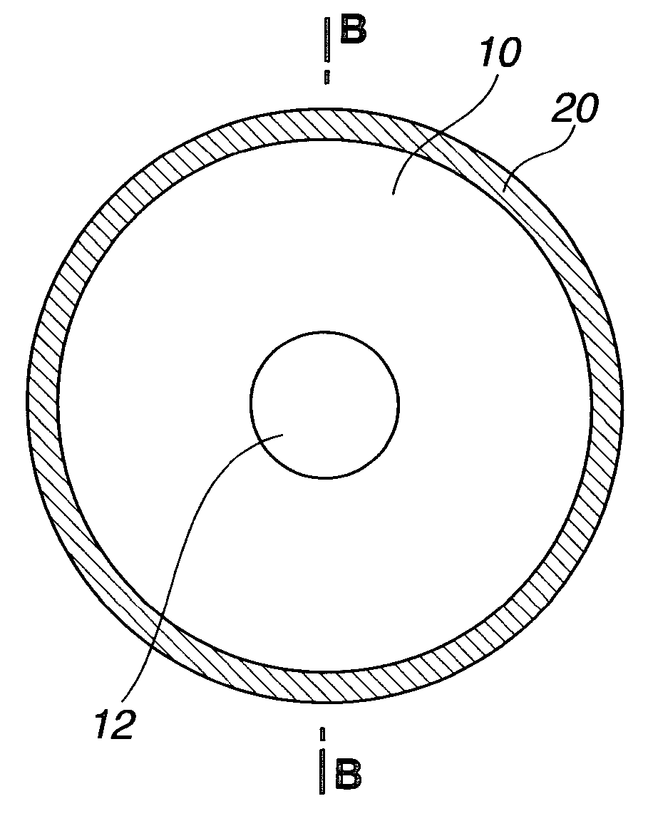
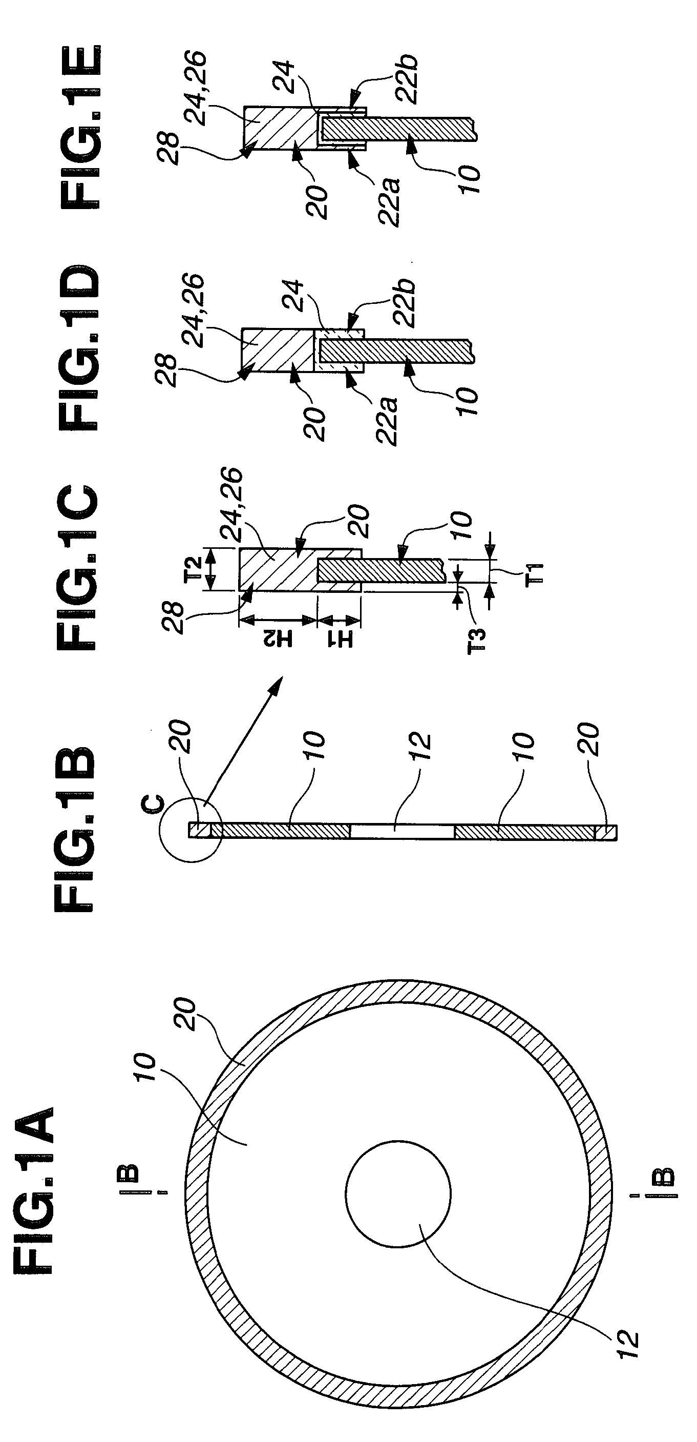
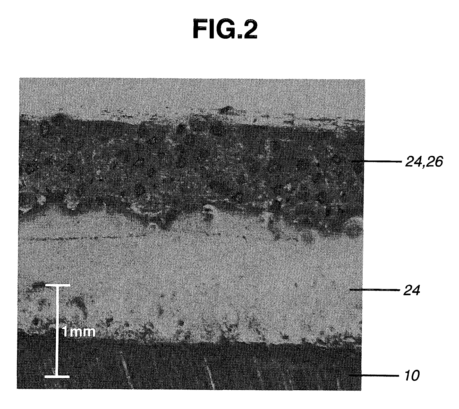
[0076]A cemented carbide consisting of 90 wt % WC and 10 wt % Co was machined into an annular thin disc having an outer diameter of 125 mm, an inner diameter of 40 mm, and a thickness of 0.3 mm, which served as a base. The base was masked with adhesive tape so that only a circumferential region of either surface extending 1.5 mm inward from the outer periphery was exposed. The base was immersed in a commercially available aqueous alkaline solution at 40° C. for 10 minutes for degreasing, washed with water, and immersed in an aqueous solution of 30 to 80 g / L of sodium pyrophosphate at 50° C. where electrolysis was effected at a current density of 2 to 8 A / dm2. The cemented carbide base was ultrasonic washed in deionized water and held by a jig for plating. In accordance with method (iv) mentioned above, nickel-clad diamond grains having an average particle size of 130 μm were disposed in contact with the periphery of the base. The base was immersed in a nickel sulfamate plating bath ...

example 2

[0077]A cemented carbide consisting of 90 wt % WC and 10 wt % Co was machined into an annular thin disc having an outer diameter of 125 mm, an inner diameter of 40 mm, and a thickness of 0.3 mm, which served as a base. The base was masked with adhesive tape so that only a circumferential region of either surface extending 1.5 mm inward from the outer periphery was exposed. The base was immersed in a commercially available aqueous alkaline solution at 40° C. for 10 minutes for degreasing, washed with water, and immersed in an aqueous solution of 30 to 80 g / L of sodium pyrophosphate at 50° C. where electrolysis was effected at a current density of 2 to 8 A / dm2. The cemented carbide base was ultrasonic washed in deionized water and held by a jig for plating. In accordance with method (iv) mentioned above, nickel-clad CBN grains having an average particle size of 130 μm were disposed in contact with the periphery of the base. The base was immersed in a nickel sulfamate plating bath at 5...

example 3

[0078]A cemented carbide consisting of 90 wt % WC and 10 wt % Co was machined into an annular thin disc having an outer diameter of 125 mm, an inner diameter of 40 mm, and a thickness of 0.3 mm, which served as a base. The base was masked with adhesive tape so that only a circumferential region of either surface extending 1.5 mm inward from the outer periphery was exposed. The base was immersed in a commercially available aqueous alkaline solution at 40° C. for 10 minutes for degreasing, washed with water, and immersed in an aqueous solution of 30 to 80 g / L of sodium pyrophosphate at 50° C. where electrolysis was effected at a current density of 2 to 8 A / dm2. The cemented carbide base was ultrasonic washed in deionized water and held by a jig for plating. As in Example 1, nickel-clad diamond grains having an average particle size of 130 μm were disposed in contact with the periphery of the base. The base was immersed in a nickel-cobalt alloy sulfamate plating bath at 50° C. where el...


PUM

PropertyMeasurementUnit
Pressureaaaaaaaaaa
Pressureaaaaaaaaaa
Pressureaaaaaaaaaa

Abstract

In an outer blade cutting wheel comprising an annular thin disc base of cemented carbide having an outer diameter of 80-200 mm, an inner diameter of 30-80 mm, and a thickness of 0.1-1.0 mm, and a blade section disposed on an outer periphery of the base, the blade section comprises diamond grains and/or CBN grains bound with a metal bond having a Young's modulus of 0.7-4.0×10¹¹ Pa and has a thickness which is greater than the thickness of the base by at least 0.01 mm. The outer blade cutting wheel is capable of cutting a workpiece at a high accuracy and a reduced allowance, improves machining yields, and reduces machining costs.

Description

CROSS-REFERENCE TO RELATED APPLICATION[0001]This non-provisional application claims priority under 35 U.S.C. §119(a) on Patent Application No. 2007-339212 filed in Japan on Dec. 28, 2007, the entire contents of which are hereby incorporated by reference.TECHNICAL FIELD[0002]This invention relates to an outer blade cutting wheel for cutting rare earth sintered magnets, and a method for preparing the same.BACKGROUND ART[0003]Outer blade cutting wheels for cutting rare earth sintered magnets are disclosed in JP-A 9-174441, JP-A 10-175171, and JP-A 10-175172 as comprising a cemented carbide base having an outer periphery to which diamond abrasive grains are bonded with phenolic resins or the like. Since diamond grains are bonded to the cemented carbide base, the base is improved in mechanical strength over prior art alloy tool steel and high-speed steel, leading to a higher accuracy of machining. Also by reducing the thickness of the blade with using a cemented carbide base, the yield o...

Claims


Application Information

Patent Timeline
IPC IPC(8): B24D11/00B28D1/24B24D5/12
CPCB23D61/028B24D3/06B24D18/0018B24D18/00B28D5/022B24D5/12B24D3/00
Inventor KASASHIMA, MASAKIMINOWA, TAKEHISAYAMAGUCHI, TAKAHARUSATO, KOJI
Owner SHIN ETSU CHEM IND CO LTD
Why Eureka
Try Eureka