

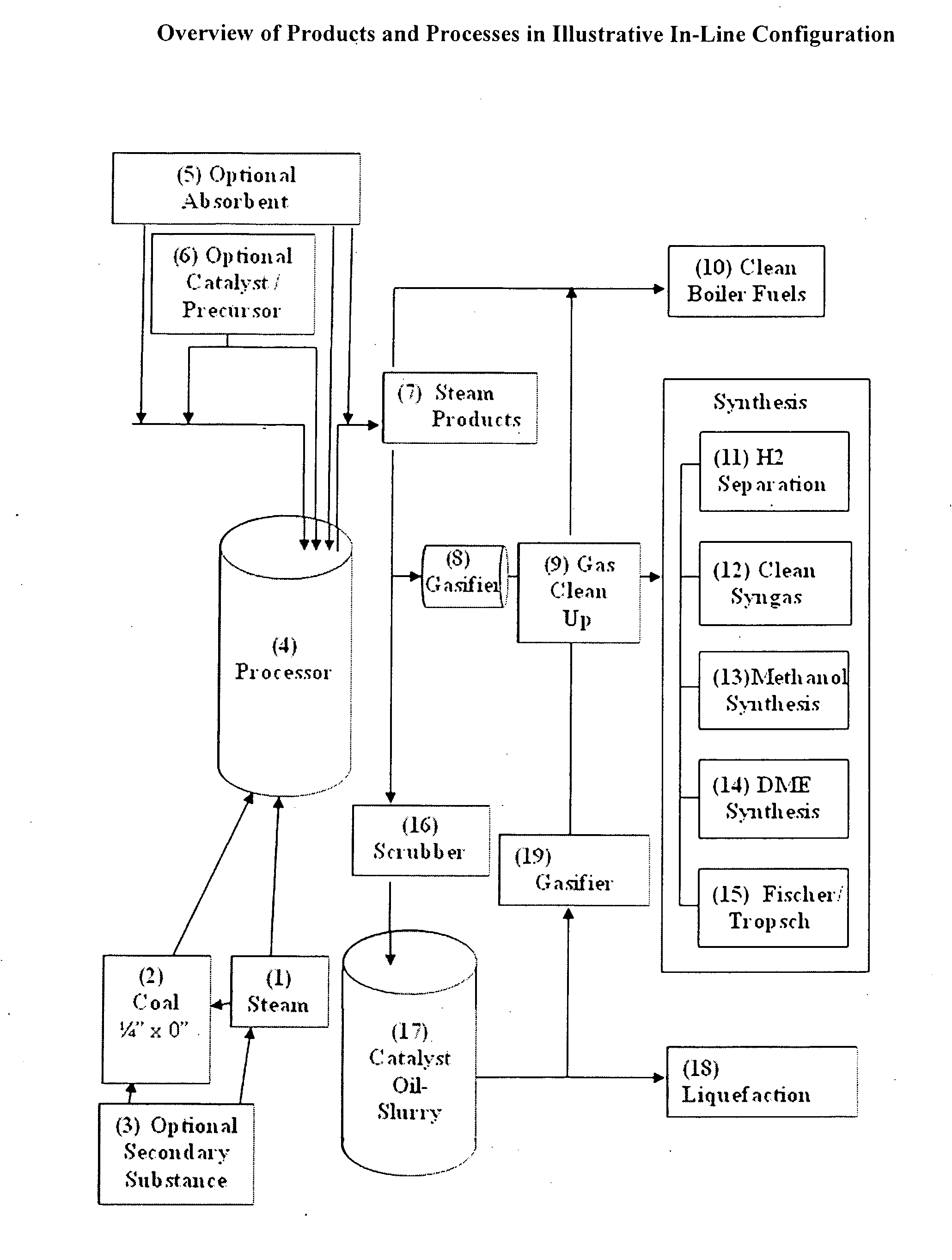
Processing device for improved utilization of fuel solids
a processing device and fuel solid technology, applied in the field of fuel solids processing devices, can solve the problems of reducing affecting the efficiency of gasification, and requiring many years for the national coal infrastructure to be retrofitted to use other types of fuels, so as to achieve rapid, uniform and fuel-efficient gasification, and reduce the wear and tear of mechanical parts.
- Summary
- Abstract
- Description
- Claims
- Application Information
AI Technical Summary
Benefits of technology
Problems solved by technology
Method used
Image

Examples
example 1
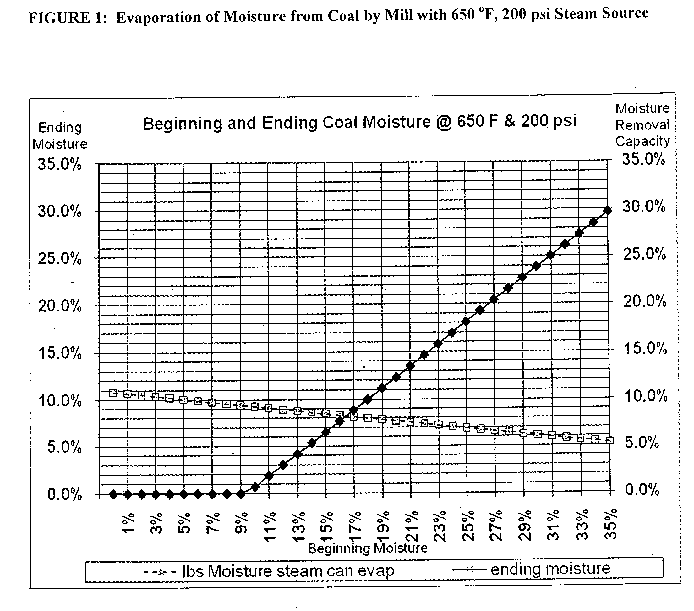
Calculations for Using a 650° F., 200 psi Steam Source.
[0230]Assumptions and figures are shown for exemplary calculations at an initial temperature of 650° F. and 200 psi in the boiler acting as a steam source for a grinder constructed according to the invention. FIG. 1 graphically depicts the result for calculating dryness of the resulting coal that is obtainable based on only the input levels of steam based on these assumptions.
Assumptions:
[0231]
Steam Conditions:650° F., 200 PSI before nozzlesInlet Temp Coal60° F.Coal / Steam Ratio0.75 lb steam / lb coalEnthalpy before nozzles1,350BTU / lb steam @ 650 / 200psi inletEnthalpy after nozzles available to1,160inside grniderheat coal and moistureEnthalpy Available190BTU / lb steam availableor enthalpy per lb of coal143BTU enthapy per poundcoal incl moistureExhaust Temperature:250° F.delta T190° F.Specific Heat Coal0.201BTU / lbheated to boiling point@250° F.Specific Heat Water1BTU / lbheated to boiling point@250° F.Evap # water at boiling961.7BTU / lbC...
example 2
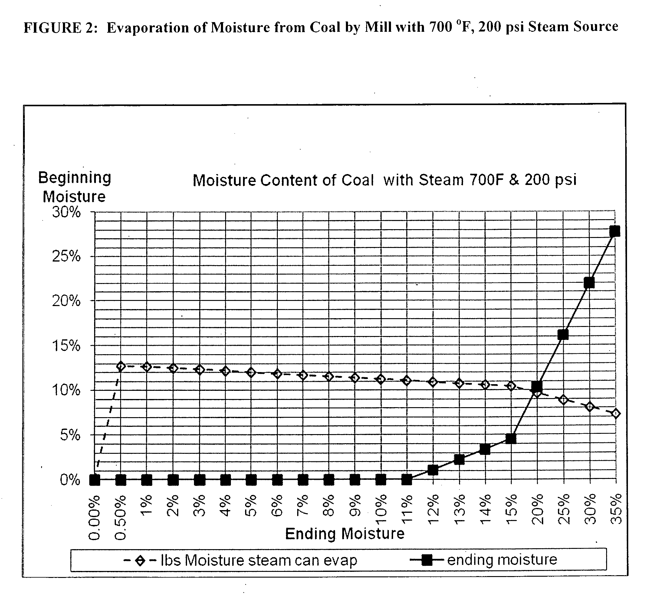
Calculations for Using a 700° F., 200 psi Steam Source.
[0232]Assumptions and figures are shown for exemplary calculations at an initial temperature of 700° F. and 200 psi in the boiler acting as a steam source for a grinder constructed according to the invention. FIG. 2 graphically depicts the result for calculating dryness of the resulting coal that is obtainable based on only the input levels of steam based on these assumptions.
Assumptions:
[0233]
Steam Conditions:700° F., 200 PSI before nozzlesInlet Temp Coal60° F.Coal / Steam Ratio0.75 lb steam / lb coalEnthalpy before nozzles1,375BTU / lb steam @ 700 / 200psi inletEnthalpy after nozzles available to1,160inside grniderheat coal and moistureEnthalpy Available215BTU / lb steam availableor enthalpy per lb of coal161BTU enthapy per poundcoal incl moistureExhaust Temperature:250° F.delta T190° F.Specific Heat Coal0.201BTU / lbheated to boiling point@250° F.Specific Heat Water1BTU / lbheated to boiling point@250° F.Evap # water at boiling961.7BTU / lbC...
example 3
Calculations for Using a 750° F., 200 psi Steam Source.
[0234]Assumptions and figures are shown for exemplary calculations at an initial temperature of 750° F. and 200 psi in the boiler acting as a steam source for a grinder constructed according to the invention. FIG. 3 graphically depicts the result for calculating dryness of the resulting coal that is obtainable based on only the input levels of steam based on these assumptions.
Assumptions:
[0235]
Steam Conditions:750° F., 200 PSI before nozzlesInlet Temp Coal60° F.Coal / Steam Ratio0.75 lb steam / lb coalEnthalpy before nozzles1,400BTU / lb steam @ 750 / 200psi inletEnthalpy after nozzles available to1,160inside grniderheat coal and moistureEnthalpy Available240BTU / lb steam availableor enthalpy per lb of coal180BTU enthapy per poundcoal incl moistureExhaust Temperature:250° F.delta T190° F.Specific Heat Coal0.201BTU / lbheated to boiling point@250° F.Specific Heat Water1BTU / lbheated to boiling point@250° F.Evap # water at boiling961.7BTU / lbC...
PUM
 Abstract
Description
Claims
Application Information