

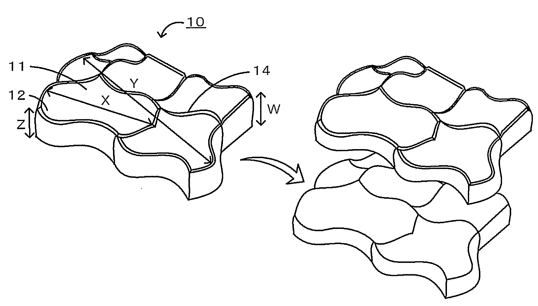
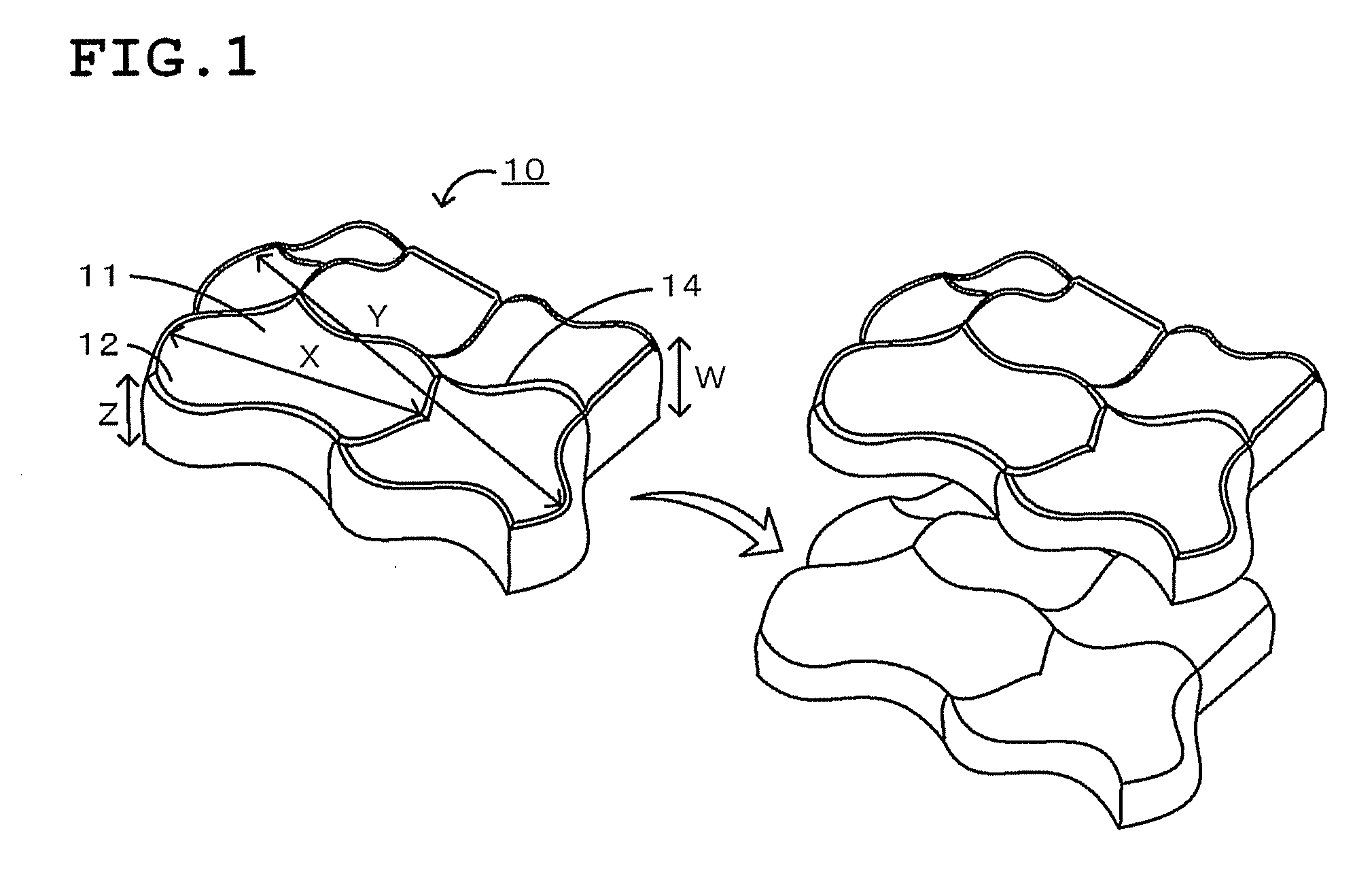
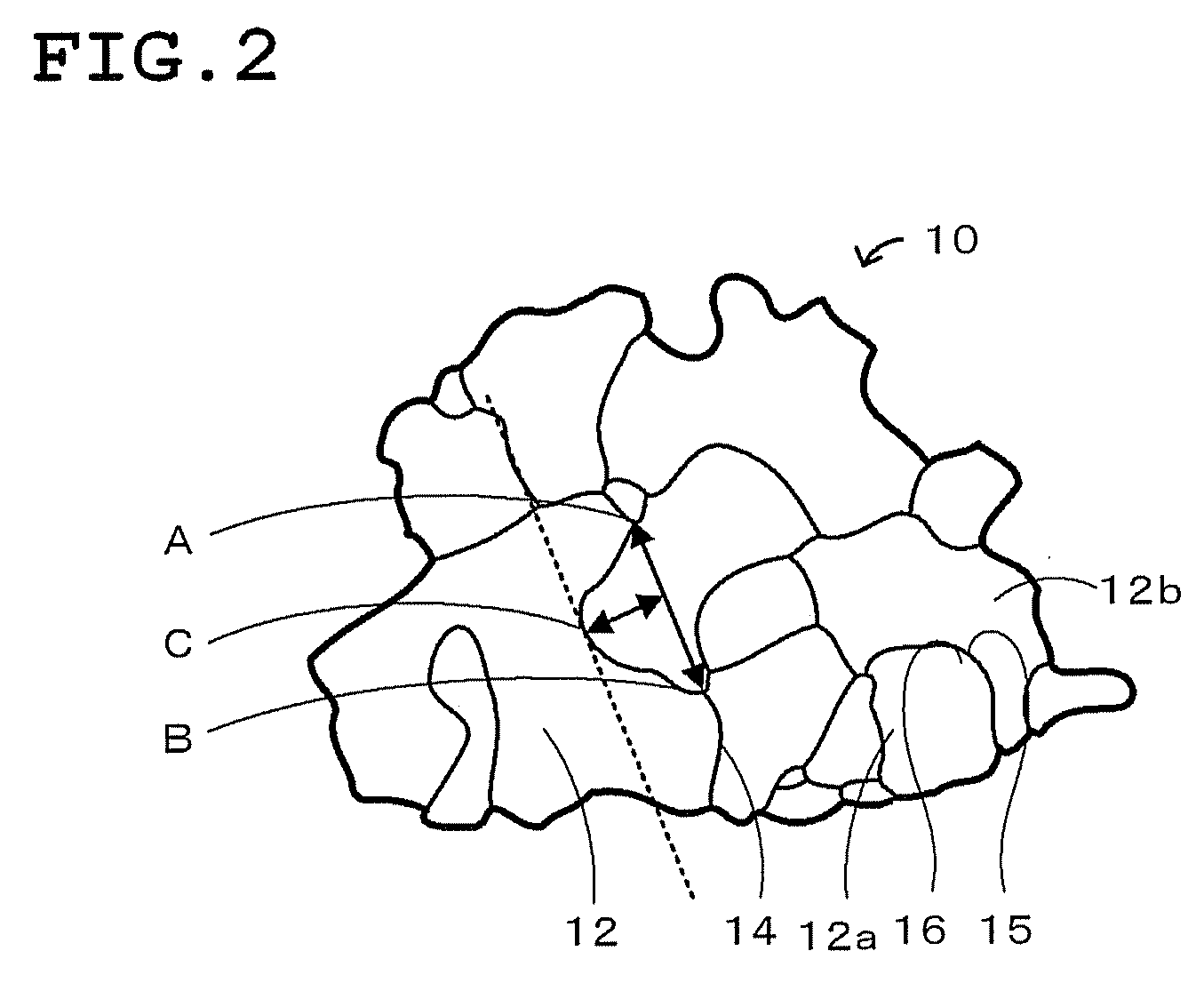
Plate-like polycrystalline particle
a polycrystalline particle and plate-like technology, applied in the field of plate-like polycrystalline particles, can solve the problems of poor sintering or low density or large particle size of a grain-oriented ceramic product, deterioration in mechanical strength or insulating properties of the ceramic product, and difficulty in altering the size and aspect ratio of the host material particle, etc., to achieve the effect of promoting the diffusion of elements, high degree of crystalline orientation, and easy modification of particle size and aspect ratio
- Summary
- Abstract
- Description
- Claims
- Application Information
AI Technical Summary
Benefits of technology
Problems solved by technology
Method used
Image

Examples
experimental example 1
Raw Material Preparation Step
[0047]A synthetic powder that was to provide a plate-like polycrystalline particle having a composition of 0.2Pb(Mg0.33Nb0.67)O3+0.35PbTiO3+0.45PbZrO3 (also referred to as basic composition 1) containing 0.002 mol MgO, zirconia balls, and ion-exchanged water, which was a dispersion medium, were charged in a polypot and were wet-blended in a ball mill for 16 hours. The resulting slurry was dried in a dryer and was calcined at 800° C. for two hours. The calcined powder, zirconia balls, and ion-exchanged water, which was a dispersion medium, were wet-grinded in a ball mill for 16 hours and were dried in a dryer to produce a powder of inorganic particles. The median diameter (D50) of the powder was 0.4 μm, as determined in a dispersion medium of water with a laser scattering particle size distribution analyzer LA-750 manufactured by HORIBA Ltd.
[0048]Forming, Firing, and Crushing Steps
[0049]A hundred parts by weight of inorganic particles, 100 parts by weight...
experimental examples 2 to 10
[0050]Plate-like polycrystalline particles according to Experimental Example 2 were manufactured in the same manner as Experimental Example 1, except that an additive component of 0.020 mol NiO substituted for the additive component of 0.002 mol MgO in the composition of the plate-like polycrystalline particles in Experimental Example 1 (0.2Pb(Mg0.33Nb0.67)O3+0.35PbTiO3+0.45PbZrO3+0.002 mol MgO). Plate-like polycrystalline particles according to Experimental Example 3 were manufactured in the same manner as Experimental Example 1, except that 0.01 mol MgO and 0.02 mol NiO (0.030 mol in total) were used as additive components. Plate-like polycrystalline particles according to Experimental Example 4 were manufactured in the same manner as Experimental Example 1, except that 0.04 mol MgO and 0.02 mol NiO (0.060 mol in total) were used as additive components. Plate-like polycrystalline particles according to Experimental Example 5 were manufactured in the same manner as Experimental Exa...
experimental examples 11 and 12
[0051]In the raw material preparation step, 0.2Pb(Mg0.33Nb0.67)O3+0.35PbTiO3+0.45PbZrO3 (basic composition 1) and 0.02 mol NiO were blended to prepare a raw material. In the firing step, firing was performed in the presence of 20 g of powder having a composition of 0.2Pb(Mg0.33Nb0.67)O3+0.35PbTiO3+0.45PbZrO3 containing 0.02 mol NiO (also referred to as firing atmosphere C). Except those, plate-like polycrystalline particles according to Experimental Example 11 was manufactured in the same manner as Experimental Example 1. Alternatively, in the raw material preparation step, 0.2Pb(Mg0.33Nb0.67)O3+0.35PbTiO3+0.45PbZrO3 (basic composition 1), 0.08 mol MgO, and 0.02 mol NiO were blended to prepare a raw material. In the firing step, firing was performed in the presence of 20 g of powder having a composition of 0.2Pb(Mg0.33Nb0.67)O3+0.35PbTiO3+0.45PbZrO3 containing 0.02 mol NiO and 0.08 mol MgO (firing atmosphere D). Except those, plate-like polycrystalline particles according to Experim...
PUM
| Property | Measurement | Unit |
|---|---|---|
| Fraction | aaaaa | aaaaa |
| Thickness | aaaaa | aaaaa |
| Length | aaaaa | aaaaa |
Abstract
Description
Claims
Application Information