
Soi transistor with floating body for information storage having asymmetric drain/source regions

a floating body and information storage technology, applied in transistors, electrical devices, semiconductor devices, etc., can solve the problems of not being able to operate with high frequency, requiring complex circuits that require relatively long access times, so as to increase the impact ionization probability, enhance the overall characteristics of storage transistors and parasitic bipolar transistors, and enhance the effect of floating body storage transistors

Inactive Publication Date: 2009-10-01
GLOBALFOUNDRIES INC
View PDF5 Cites 63 Cited by
  • Summary
  • Abstract
  • Description
  • Claims
  • Application Information

AI Technical Summary

Benefits of technology

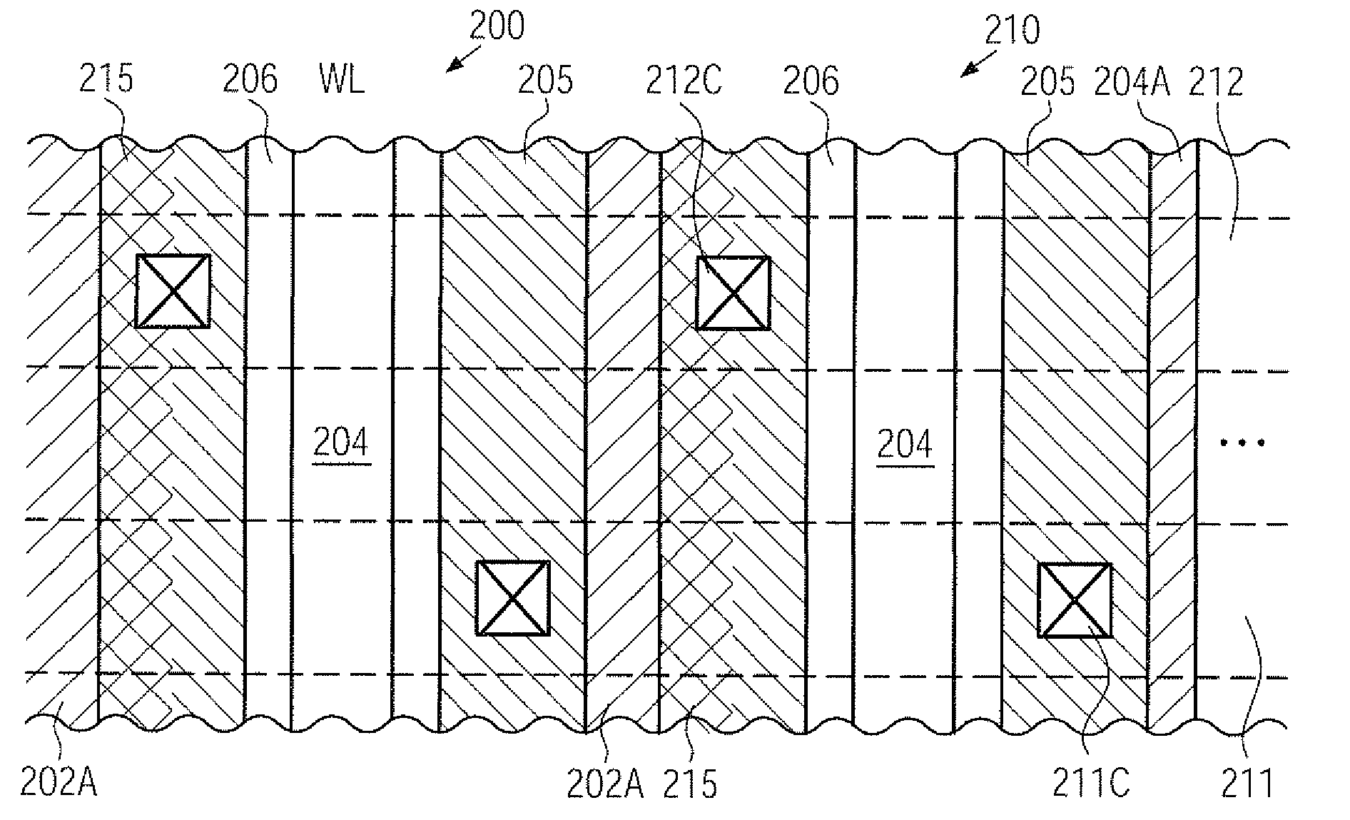
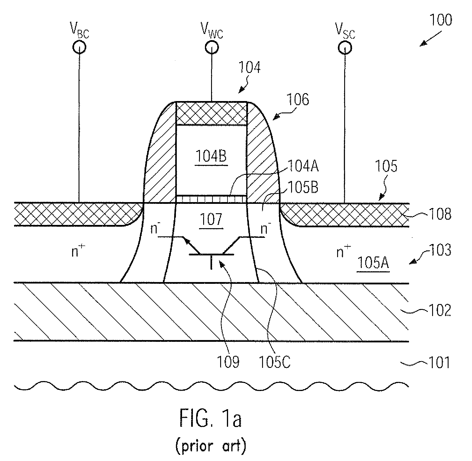
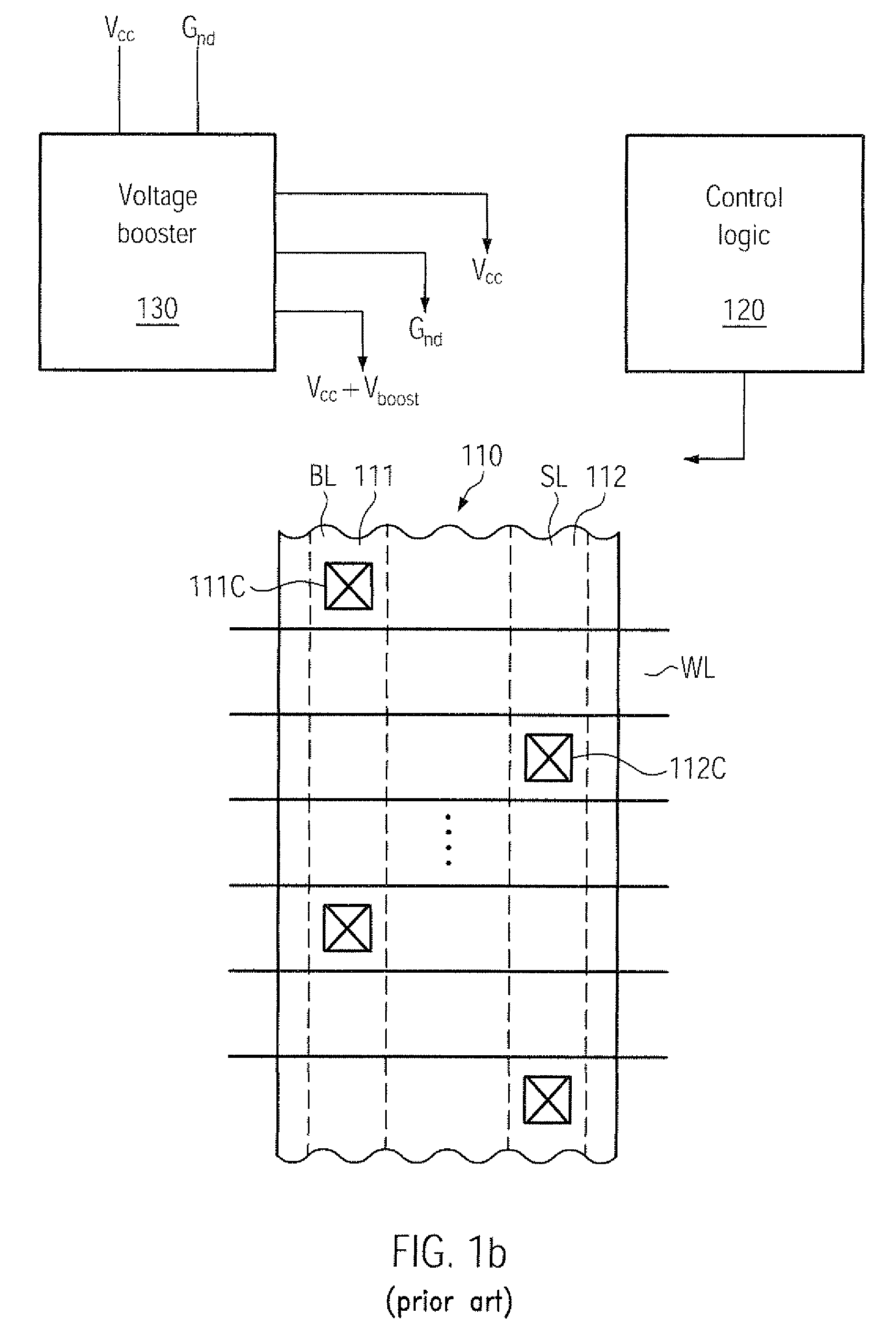
[0016]Generally, the subject matter disclosed herein relates to semiconductor devices and techniques in which performance of floating body storage transistors may be enhanced by appropriately adapting the characteristics of a parasitic bipolar transistor and increasing the impact ionization probability locally at the drain side of the storage transistor. For this purpose, the basic doping of the well region may be accomplished in a laterally asymmetric manner with respect to drain and source areas, for instance, by appropriately providing implantation conditions so as to laterally asymmetrically pattern the well dopant concentration, so that the overall characteristics of the storage transistor and the parasitic bipolar transistor may be enhanced. That is, in the floating body region of the storage transistor, the basic well dopant concentration may be adapted so as to maintain the low concentration level for reducing the probability for charge carrier re-combination, which may be advantageous in maintaining a desired charge storage in the floating body. On the other hand, the probability of impact ionization may be locally increased at the drain side, thereby increasing the probability of creating charge carriers during the operation of the storage transistor, which may also result in a more efficient switching on of the parasitic bipolar transistor at reduced collector / emitter voltages compared to conventional designs. Consequently, reduced operating voltages for the storage transistor, possibly in combination with enhanced scalability thereof, may result in an overall performance enhancement of floating body storage transistors.

Problems solved by technology

For this reason, highly complex circuits have been developed, which may include different types of circuits, such as analog circuits, digital circuits and the like, thereby providing entire systems on a single chip (SoC).
However, usage of storage capacitors may require a regular refreshing of the charge stored in the capacitor while also writing to and reading from the dynamic RAM memory cell may require relatively long access times to appropriately charge and discharge the storage capacitor.
Thus, although a high information storage density is provided, in particular, when vertical storage capacitor designs are considered, these memory devices may not be operated with high frequency and, therefore, dynamic RAM memories may typically be used for chip internal memories, for which an increased access time may be acceptable.
This configuration provides significant advantages, but also gives rise to a plurality of issues.
The floating body effect is considered disadvantageous for the operation of regular transistor elements, in particular for static RAM memory cells, since the operation-dependent threshold voltage variation may result in significant instabilities of the memory cell which may not be tolerable in view of data integrity of the memory cell.
In addition, by applying a moderately high voltage to the transistor 100, respective leakage currents may also increase, thereby negatively impacting the retention time of the transistor 100.

Method used


Image

  • Soi transistor with floating body for information storage having asymmetric drain/source regions
  • Soi transistor with floating body for information storage having asymmetric drain/source regions
  • Soi transistor with floating body for information storage having asymmetric drain/source regions

Examples


Embodiment Construction

[0031]Various illustrative embodiments of the invention are described below. In the interest of clarity, not all features of an actual implementation are described in this specification. It will of course be appreciated that in the development of any such actual embodiment, numerous implementation-specific decisions must be made to achieve the developers' specific goals, such as compliance with system-related and business-related constraints, which will vary from one implementation to another. Moreover, it will be appreciated that such a development effort might be complex and time-consuming, but would nevertheless be a routine undertaking for those of ordinary skill in the art having the benefit of this disclosure.

[0032]The present subject matter will now be described with reference to the attached figures. Various structures, systems and devices are schematically depicted in the drawings for purposes of explanation only and so as to not obscure the present disclosure with details ...


PUM


Abstract

By laterally asymmetrically defining the well dopant concentration in a floating body storage transistor, an increased well dopant concentration may be provided at the drain side, while a moderately low concentration may remain in the rest of the floating body region. Consequently, compared to conventional symmetric designs, a reduction in the read / write voltages for switching on the parasitic bipolar transistor may be accomplished, while the increased punch-through immunity may allow further scaling of the gate length of the floating body storage transistor.

Description

BACKGROUND OF THE INVENTION[0001]1. Field of the Invention[0002]Generally, the present disclosure relates to the field of integrated circuits, and, more particularly, to field effect transistors in complex circuits which may include a memory area formed according to an SOI architecture, wherein information is stored by controlling charge in a floating body of an SOI transistor.[0003]2. Description of the Related Art[0004]Integrated circuits typically comprise a great number of circuit elements on a given chip area according to a specified circuit layout, wherein advanced devices may comprise millions of signal nodes that may be formed by using field effect transistors or MOS transistors. In the context of the present disclosure, the terms field effect transistors and MOS transistors are considered as synonyms. Thus, field effect transistors may represent a dominant component of modern semiconductor products, wherein advances in performance and low integration volume are mainly assoc...

Claims


Application Information

Patent Timeline
IPC IPC(8): H01L29/66H01L21/336
CPCH01L21/26586H01L21/84H01L27/108H01L29/7841H01L27/1203H01L29/1087H01L27/10802H10B12/20H10B12/00
Inventor VAN BENTUM, RALFMOHAPATRA, NIHAR-RANJAN
Owner GLOBALFOUNDRIES INC
Learn More