Shielded three-terminal flat-through emi/energy dissipating filter

Active Publication Date: 2009-10-01
WILSON GREATBATCH LTD
View PDF56 Cites 155 Cited by
  • Summary
  • Abstract
  • Description
  • Claims
  • Application Information

AI Technical Summary

Benefits of technology

[0044]A primary object of the present invention is to provide a novel shielded three-terminal flat-through EMI/energy dissipating filter which embodies one or more flat-through capacitors whose internal electrodes are high frequency shielded, are much thicker (compared to prior art MLCC flat-through thick film electrode technology) and higher in both cross-sectional and surface area (robust and able to carry much higher through circuit currents), whose electrodes can be configured with integral co-planar inductor elements, and can be optionally configured to accept a variety of surface mounted electronic components (like additional discrete or embedded capacitors, inductors, diodes, RFID chips, and the like). The higher surface area of the novel shielded three-terminal flat-through EMI/energy dissipating filter of the present invention maximizes the value of the flat-through capacitance. The present invention resides in a shielded three-terminal flat-through EMI/energy dissipating filter which comprises an active electrode plate through which a circuit current passes between a first terminal and a second ter

Problems solved by technology

These devices tend to be more sensitive to EMI than passive pumps that have no sense circuitry or externally implanted lead wires.
Cell phones, microwave ovens and the like have all been implicated in causing interference with active implantable medical devices.
However, as the MLCC nears its self-resonant frequency (SRF), its attenuation tends to go up dramatically.
This is an undesirable effect and this is why feedthrough capacitors have generally been the preferred choice for use in EMI broadband filters.
Referring once again to FIG. 19, the reason why this approach has never been commonly practiced in the AIMD market is the fact that this is a complicated design and is also costly.
Because of the space limitations and reliability implications, packing this many components into such a small place becomes impractical.
In the industry, this is known as the tombstone mounting position, which is a highly undesirable thing to do when the capacitor is to be used as an EMI filter or an RF decoupling device (bad mounting and bad form factor).
The reason this is undesirable is this particular capacitor will tend to self-resonate at a much lower frequency (and thereby becomes a less effective hi

Method used


Image

  • Shielded three-terminal flat-through emi/energy dissipating filter
  • Shielded three-terminal flat-through emi/energy dissipating filter
  • Shielded three-terminal flat-through emi/energy dissipating filter

Examples


Example

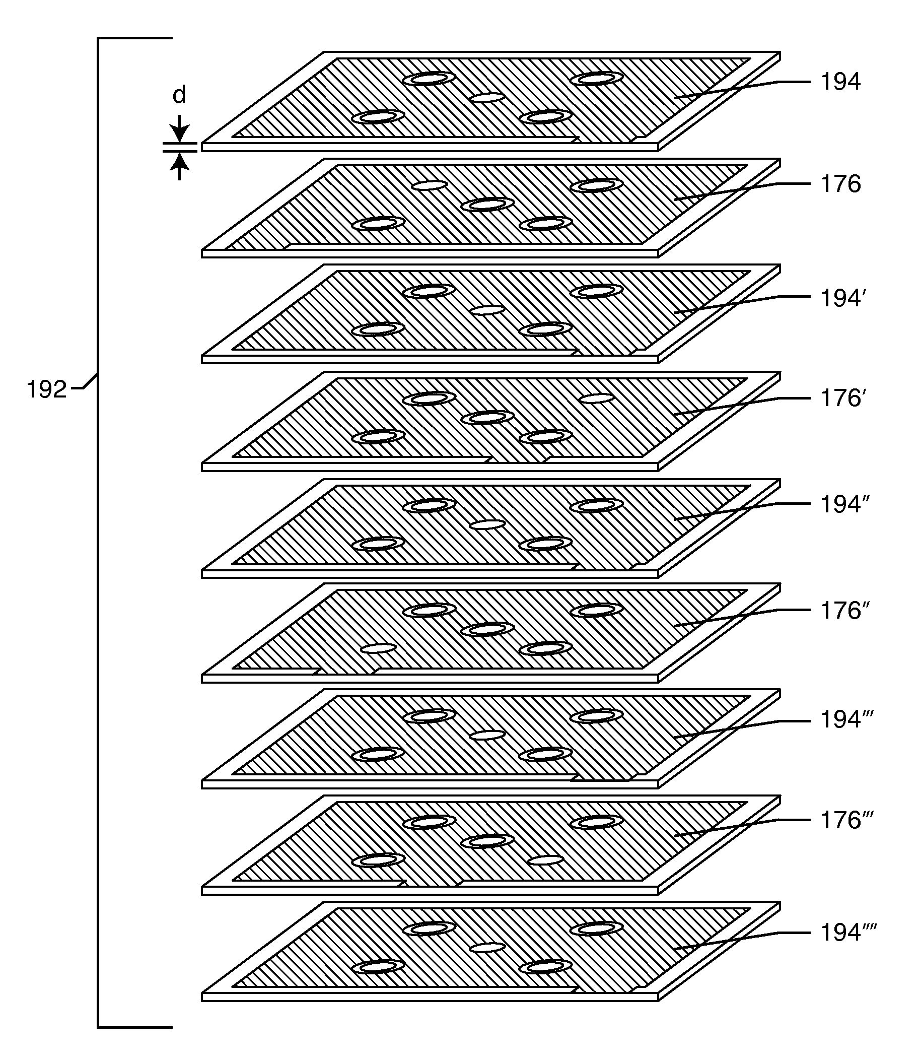
[0204]As shown in the drawings for purposes of illustration, the present invention is concerned with shielded three-terminal flat-through EMI / energy dissipating filters 190 which can be embodied in substrates or flex cable assemblies. The novel concept resides in designing an embedded flat-through capacitor wherein optional surface mounted passive or active components can be attached while at the same time providing an interconnection circuit. The novel shielded three-terminal flat-through EMI / energy dissipating filters 190 embody a flat-through capacitor that has similar characteristics to prior art feedthrough EMI filter capacitors. The flat-through EMI / energy dissipating filter 190 of the present invention provides three-terminal capacitive filtering while simultaneously providing shielding of circuits and signals passing through the robust high current capability electrodes of the flat-through capacitor. The flat-through EMI / energy dissipating filter 190 of the present invention...


PUM


Abstract

A shielded three-terminal flat-through EMI/energy dissipating filter includes an active electrode plate through which a circuit current passes between a first terminal and a second terminal, a first shield plate on a first side of the active electrode plate, and a second shield plate on a second side of the active electrode plate opposite the first shield plate. The first and second shield plates are conductively coupled to a grounded third terminal. In preferred embodiments, the active electrode plate and the shield plates are at least partially disposed with a hybrid flat-through substrate that may include a flex cable section, a rigid cable section, or both.

Description

BACKGROUND OF THE INVENTION[0001]The present invention relates generally to feedthrough filter capacitor EMI filters. More particularly, the present invention relates to a hybrid EMI filter substrate and / or flex cable assembly which embody embedded shielded flat-through / feedthrough filters and / or energy dissipating circuit elements. This invention is applicable to a wide range of connectors, terminals and / or hermetic seals that support lead wires as they ingress / egress into electronic modules or shielded housings. In particular, the present invention applies to a wide variety of active implantable medical devices (AIMDs).[0002]FIGS. 1-40 provide a background for better understanding the significance and novelty of the present invention.[0003]FIG. 1 illustrates various types of active implantable and external medical devices 100 that are currently in use. FIG. 1 is a wire formed diagram of a generic human body showing a number of implanted medical devices. 100A represents a family of...

Claims


Application Information

Patent Timeline
IPC IPC(8): H03H7/00
CPCA61N1/3754H01G4/40H01R13/7195H03H1/0007H01G4/35H05K9/00H05K5/0095H03H2001/0085H03H7/1766A61N1/08A61N1/375A61N1/3718A61N2001/086H03H2001/0042A61N1/086H05K1/181H05K2201/10015H01G4/06H05K999/99
Inventor STEVENSON, ROBERT A.TRUEX, BUEHL E.BRENDEL, RICHARD L.FRYSZ, CHRISTINE A.DABNEY, WARREN S.HUSSEIN, HAYTHAMADAME, JOSE LUIS LORENTEJOHNSON, ROBERT SHAWNBRAINARD, SCOTT
Owner WILSON GREATBATCH LTD
Why Eureka
Try Eureka