
Apparatus for desalinization utilizingtemperature gradient/condensation and method thereof

a technology of desalinization apparatus and temperature gradient, which is applied in the direction of vacuum distillation separation, vessel construction, separation process, etc., can solve the problems of large scale desalinization, low efficiency, and inability to disclose the use of lowering pressure to allow for easy evaporation of saltwater, etc., and achieve high efficiency

Inactive Publication Date: 2009-10-15
LONGER DAVID E
View PDF5 Cites 3 Cited by
  • Summary
  • Abstract
  • Description
  • Claims
  • Application Information

AI Technical Summary

Benefits of technology

[0006]The present disclosure addresses the above mentioned problems with an apparatus for the desalinization of salt water utilizing a humidity chamber under partial vacuum and a water collection structure to collect fresh water product. Saltwater having a first temperature and cooling water contained in a condenser having a second temperature lower than the first temperature are introduced into the humidity chamber. A temperature gradient created by a difference in temperature between the saltwater and cooling water in combination with a partial vacuum (e.g., 10-20%) is used to distill salt-free water from the saltwater with high efficiency. The temperature gradient is created in part by the use of a salinity gradient solar pond which heats the salt water to be purified in an economic and pollution free manner. The salt-free water is obtained by condensation of the water on a collection surface cooled by the cooling water followed by collection of the water in a storage apparatus. The evaporation of the water is expedited by the use of a solar powered vacuum pump.
[0012]In another embodiment of the present disclosure, a warm water heat exchanger in which water is heated to temperatures as high as 180-190° F. is used to raise the temperature of the salt water. The warm water heat exchanger supplies warm water from a salinity gradient solar pond. A salinity gradient solar pond generally is a body of water that collects and stores solar energy. The salinity gradient pond utilizes the relatively high density of saline over salt-free water to prevent the natural convection of solar heated water. The density of water increases with increasing concentration of salt. Typically, when water is heated, it becomes less dense and rises to the surface of the body of water. However, if the heated water is more dense than the layer of water above, the water will not rise. Accordingly, convection may be significantly reduced or eliminated by having layers of varying salinity.
[0013]A typical salinity gradient solar pond contains three layers: an upper surface layer is cold and is homogeneous with no or low salt content; the bottom layer is hot and homogeneous with a high salt content and therefore is dense and will not rise. The middle gradient layer has a salt content that increases with increasing depth of the pond. In the middle gradient layer, water cannot rise because water above it is lighter, and it cannot fall because the water beneath it is heavier. As a result, the stable gradient layer suppresses convection and acts as a transparent insulator, permitting sunlight to penetrate the upper two layers and heat the bottom layer as well as reducing heat loss from the bottom layer to the upper layer. The heat in the bottom layer can then be withdrawn by pumping the hot brine through an external heat exchanger or by pumping a heat transfer fluid, for example fresh water, through a heat exchanger placed on the bottom of the pond. Salinity gradient solar ponds have the potential to produce low cost thermal energy from a renewable source at large scale for industrial applications. This is due in part to the ability of salinity gradient solar pond to function as a heat storage device. Thus, the solar pond is capable of producing and retaining heat 24 hours per day throughout the summer and winter months.
[0014]As a result from the use of the salinity gradient solar pond, a temperature gradient of from 10 to 70° C. can result between the heated saltwater to be purified and the cooling water which is maintained at a temperature range over a period of time varying from 15 to 70° C. at low cost and low impact to the environment.
[0016]In one embodiment of the present disclosure, the pressure of the humidity chamber is decreased by use of a solar powered vacuum pumping system. The solar powered vacuum pump is designed to move water through the closed loop hot and cold heat exchangers. The vacuum is created by the solar powered pumps by creating vacuum in a large cylinder during the day when the pumps receive energy to run, and then the vacuum is stored in the cylinder for night time operations of the water in the heat exchangers. Air is evacuated from the chamber such that the atmospheric pressure is reduced by 10-20%. This pressure lowering is sufficient to increase the rate at which water evaporates and condenses within the humidity chamber.

Problems solved by technology

Regions without access to fresh water must either import water, a very costly endeavor, or develop methods to generate fresh water.
However, in order to provide enough fresh water for a medium to large size city, desalinization on a large scale must be performed.
Large-scale desalination typically requires large amounts of energy as well as specialized, expensive infrastructure, making it very costly compared to the use of fresh water from rivers or groundwater.
However, it does not disclose use of lowering pressure to allow for easier evaporation of saltwater, or the use of solar powered vacuum pumps to save fossil fuels.

Method used


Image

  • Apparatus for desalinization utilizingtemperature gradient/condensation and method thereof
  • Apparatus for desalinization utilizingtemperature gradient/condensation and method thereof
  • Apparatus for desalinization utilizingtemperature gradient/condensation and method thereof

Examples


embodiment 150

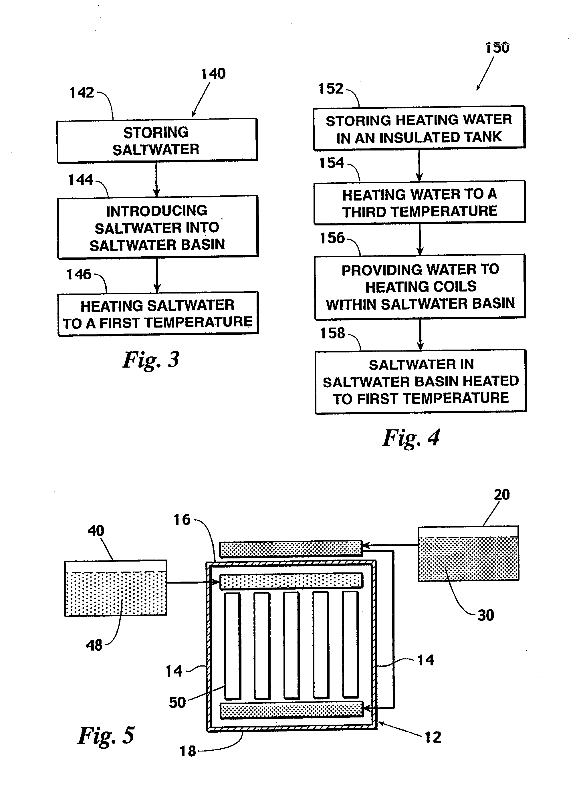
[0039]FIG. 4 illustrates a schematic of an embodiment 150 to heat saltwater located within the saltwater basin. As illustrated in steps 152 and 154, water is heated by a flat plate solar collector and stored in an insulated tank or obtained from a salinity gradient solar pond. The heated water is then released in to heating coils located within the saltwater basin residing in the humidity chamber, as illustrated in steps 156. The saltwater located within the saltwater basin is then heated via the heated water to an acceptable temperature for evaporation as illustrated in steps 158. While the close loop heating process is illustrated as being used independently, those skilled in the art will recognize that this process can be used in combination with other heating processes, such as the thermal tube heating process.

embodiment 10

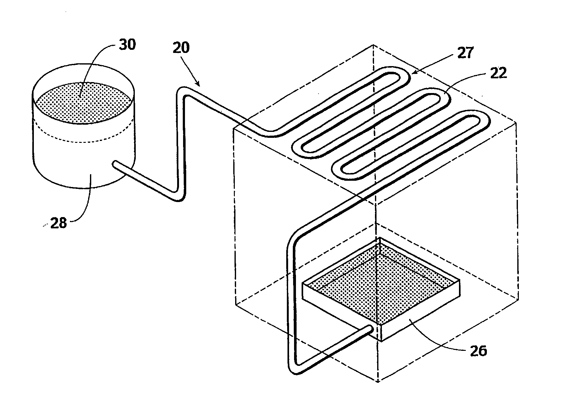
[0040]As shown in FIG. 5, an embodiment 10 of the apparatus comprises a humidity chamber 12, a saltwater container 20, a cooling water container 40 and a salt-free water collecting container 50. Saltwater container 20 provides saltwater 30 having a first temperature into humidity chamber 12. Cooling water container 40 provides cooling water 48 having a second temperature, which is relatively cooler than the temperature of the saltwater, into humidity chamber 12. The temperature difference between saltwater 30 and cold water 48 creates a temperature gradient which establishes suitable atmospheric conditions for the evaporation of the saltwater. During this evaporation process, salt-free water evaporates into water vapor while the salt and salt-related constituent compounds do not. The salt-free water vapor then condenses on salt-free water condensing and collection container 50. The salt-free water condensation is then collected for later use.

[0041]Humidity chamber 12 is shown in a g...


PUM

PropertyMeasurementUnit
Temperatureaaaaaaaaaa

Abstract

An apparatus and method for the desalinization of salt water utilizing a humidity chamber under partial vacuum and a water collection structure to collect fresh water product. Saltwater having a first temperature and cooling water contained in a condenser having a second temperature lower than the first temperature are introduced into the humidity chamber via a solar powered vacuum pump. A temperature gradient created by a difference in temperature between the saltwater and cooling water in combination with a partial vacuum (e.g., 10-20%) created by a solar powered vacuum pump is used to distill salt-free water from the saltwater with high efficiency. The temperature gradient is created in part by the use of a salinity gradient solar pond. The salt-free water is obtained by condensation of the water on a collection surface cooled by the cooling water followed by collection of the water in a storage apparatus.

Description

CROSS REFERENCE TO PROVISIONAL APPLICATION[0001]This application is based upon and claims the benefit of priority from U.S. Provisional Patent Application No. 61 / 040,569 (Attorney Docket No. 081793-0011) filed on Mar. 28, 2008, the entire contents of which are incorporated by reference herein.FIELD OF DISCLOSURE[0002]This disclosure relates to the field of salt-water purification via evaporative desalinization of salt water.BACKGROUND[0003]Fresh water is a fundamental requirement for modern day societies. Without convenient access to fresh water, resources normally spent in day-to-day activities forwarding the progress of civilization are directed to acquiring water for basic survival. Regions without access to fresh water must either import water, a very costly endeavor, or develop methods to generate fresh water. One method of water generation is desalinization of salt water.[0004]However, in order to provide enough fresh water for a medium to large size city, desalinization on a ...

Claims


Application Information

Patent Timeline
IPC IPC(8): C02F1/14
CPCB01D1/0035B01D5/0039C02F1/06C02F2209/03C02F2103/08C02F2209/02C02F1/14Y02A20/124Y02A20/142Y02A20/212
Inventor LONGER, DAVID E.
Owner LONGER DAVID E
Learn More