High retardation-amplitude photoelastic modulator

a photoelastic modulator and retardation amplitude technology, applied in the field of photoelastic modulators, can solve the problems of difficult to achieve spectral resolutions useful in the mid-infrared (smaller than tens of cmsup>1/sup>), limit the usefulness of light analysis applications where the intensity of light to be analyzed is low, and increase the length of the photoelastic bar. , the effect of complexity

Inactive Publication Date: 2009-10-22
BUICAN TUDOR N
View PDF10 Cites 8 Cited by
  • Summary
  • Abstract
  • Description
  • Claims
  • Application Information

AI Technical Summary

Benefits of technology

[0013]Accordingly, it is an object of the present invention to provide an elongated photoelastic modulator, wherein polarized light traveling in the long direction thereof and with its direction of polarization parallel to a principal axis of the modulator experiences an integrated retardation that increases with increasing length of the photoelastic modulator.
[0014]Another object of the present invention is to provide an elongated photoelastic modulator, wherein polarized light traveling in the long direction thereof and with its direction of polarization parallel to a principal axis of the modulator experiences an integrated retardation that increases with increasing length of the photoelastic modulator for use in interferometry.
[0019]The embodiments of the present invention overcome the disadvantages and limitations of a stack of isolated resonators oscillating at their fundamental frequencies which include the requirement of a set of expensive finished windows having prohibitive light losses. The benefits and advantages thereof include, but are not limited to, providing a low-light loss photoelastic modulator having the potential for arbitrarily high birefringence; that is, a birefringence that increases with increasing length of the photoelastic bar, but that may have limitations related to the complexity, cost and inefficiencies inherent in a very long bar having a large number of piezoelectric transducers.

Problems solved by technology

This difference in phase velocity results in a phase difference (retardation) between the two components.
PEM / FT spectrometers are capable of providing greater than 105 interferograms / spectra scanned per second, as opposed to a few thousand scans / s available with the fastest non-PEM interferometers; however, achieving spectral resolutions useful in the mid-infrared (smaller than tens of cm−1) is difficult.
However, because of light losses at the optical interfaces, such a system has a limited light throughput (estimated by the present inventor to be between 3-8%) which limits its usefulness in applications where the intensity of the light to be analyzed is low.
This limitation may not be important in applications where either a high-intensity light source is available, or large-aperture collection optics can be used.
However, in some applications, the intensity of the available light is small and few photons can be captured in the short time available to an ultra-high-speed instrument.
However, this approach fails where the equivalent of the individual windows are no longer physically separated, but rather are in direct contact with each other in the bar, since elastic waves can now travel along the length of the bar.

Method used


Image

  • High retardation-amplitude photoelastic modulator
  • High retardation-amplitude photoelastic modulator
  • High retardation-amplitude photoelastic modulator

Examples


example 1

Active Wave Containment

[0049]FIG. 6A shows a point source that generates a wave that propagates in a medium along the x-axis and that has an amplitude, A(x), phase, φ(x), angular frequency ω, and attenuation β. Waves propagating to the left and right of the interval are given by:

L(x,t)=A0eiφ0ei(ωt+κ(x−x0))=A0e(ωt+κ(x−x0)), and

[0050]R(x,t)=A0eiφ0ei(wt−κ(x−x0))=A0ei(wt−κ(x−x0)) where A0=A(x0), φ0=φ(x0) are respectively the amplitude and phase of the left- and right-propagating waves at the source, A0=A0eiφ0 is the complex amplitude of the two waves at the source, ω is the angular frequency of the oscillation, and κ is the complex wavenumber κ=ω / c−iβ=2π / λ−iβ=k−iβ, where c is the phase velocity of the waves along the x axis, β is the attenuation coefficient, λ is the wavelength of the elastic wave, and k=2π / λ is the (real) wavenumber.

FIG. 6B shows a set of N point sources positioned at xj(i=1, . . . N), oscillating with the same angular frequency ω and generating N waves having amplitud...

example 2

Active Reflector

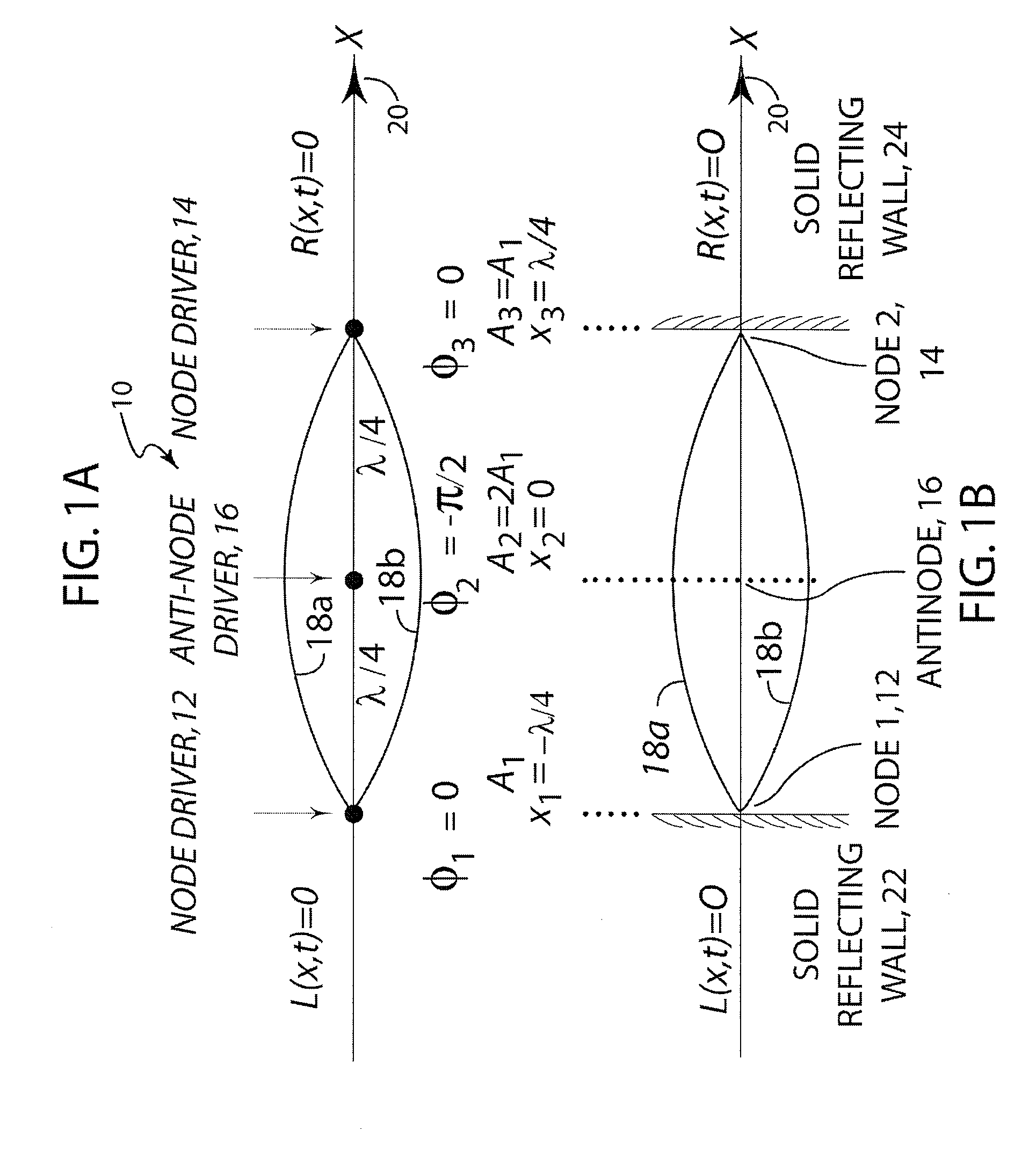
[0053]For N=2, Equation 2 can be written as:

−A2 / A1=−eiκ(x2−x1)=ei(k(x2−x1)+π)eβ(x2−x1).

In terms of amplitudes and phases, this is equivalent to A2 / A1=eβ(x2−x1) and φ2−φ1=k(x2−x1)+π. These relationships between the amplitudes and the phases of the two sources result in no wave propagating to the left of source 1. In particular, for a source separation of a quarter wavelength, x2−x1=λ / 4, and no attenuation (β=0), the condition for containment to the left is A1=A2=A (equal amplitudes) and φ2−φ1=−π / 2; that is, the second source must lag in phase by π / 2 relative to the first source.

[0054]FIG. 7A shows two such point sources oscillating in quadrature, and separated by π / 4, where the second source lags in phase by π / 2 behind the first source. Thus, the wave to the left of the source vanishes, while the right propagating wave has an amplitude which, in the absence of attenuation, is the sum of the two source amplitudes, the sources adding constructively provided that there i...

example 3

Isolated Active Resonant Cell

[0055]If Equation 2a has a nonzero solution, then both waves propagating outside the region containing sources vanish and the elastic wave is contained within a bounded region which, under the right conditions, will act as a virtual active resonator. This is called and Active Resonance Cell, or ARC.

[0056]For two sources N=2, the vector equation 2a has nonzero solutions if and only if the determinant of the 2×2 matrix of exponentials vanishes:

det[-κx1-κx2κx1κx2]=κ(x2-x1)--κ(x2-x1)=0,

which holds if and only if β=0 (no attenuation), and x2−x1=nλ / 2 (the standard standing wave condition for two mirrors placed at x1 and x2). In other words, active wave confinement for N=2 requires strict geometric and propagation conditions if oscillations are to be confined to the region defined by the two sources. The geometric condition is identical to that for a standard resonant cavity between two mirrors; further, oscillations will not be confined if there is a non-zero ...


PUM


Abstract

A photoelastic modulator excited by a plurality of piezoelectric transducers affixed to the surface of a photoelastic bar for generating elastic waves in a plurality of cells each bounded by piezoelectric node drivers between which an antinode driver is disposed, is described. The standing elastic wave in each cell can be made independent of those in the neighboring cells by controlling the phase and amplitude of the drivers. The resulting elastic waves generate birefringence along the optical axis of the bar such that a linearly polarized optical wave propagating along the axis and having an initial phase, experiences a retardation of the phase as it passes through each cell. The cells may be controlled such that the phase of each standing wave does not change between cells and the phase retardation of the optical wave increases monotonically as the optical wave propagates through the bar, thereby, in theory, permitting an arbitrarily large retardation to be generated.

Description

FIELD OF THE INVENTION[0001]The present invention relates generally to photoelastic modulators and, more particularly to high retardation-amplitude photoelastic modulators.BACKGROUND OF THE INVENTION[0002]Birefringent optical materials exhibit a refractive index that varies with the direction of polarization of the incident light, and are characterized by the difference between the maximum and minimum values of the refractive index, and by the directions of polarization along principal axes corresponding to these extreme values. Retardation is the phase difference introduced between waves polarized along the principal axes resulting from travel through the birefringent material, and is proportional to the birefringence, the distance traveled by the light through the material, and to the frequency of the light. It may be expressed in “waves” at some given wavelength; that is, a phase difference of 2π radians times the number of “waves” at the given (vacuum) wavelength.[0003]Isotropic...

Claims


Application Information

Patent Timeline
Patent Type & Authority Applications(United States)
IPC IPC(8): G02B27/00
CPCG02F1/0131G02F2202/40G02F1/0136
Inventor BUICAN, TUDOR N.
Owner BUICAN TUDOR N
Why Eureka
Try Eureka