Light-emission lens, light-emitting element assembly, sheet-shaped light source device and color liquid crystal display assembly

a technology of light-emitting elements and assembly, which is applied in the direction of lenses, lighting and heating apparatus, instruments, etc., can solve the problems of high throughput production and lens defects, and achieve the effect of high productivity, simple shape and mass production

Inactive Publication Date: 2009-11-05
SONY CORP
View PDF5 Cites 44 Cited by
  • Summary
  • Abstract
  • Description
  • Claims
  • Application Information

AI Technical Summary

Benefits of technology

[0051]In the first- or second-mode embodiment of the present invention, the lens is formed from only the circular bottom face, lateral face formed from an aspheric surface and top face formed from an aspheric surface. In the third-mode embodiment of the present invention, the lens is formed from by the circular bottom face, lateral face formed from the rotational symmetric curved surface convexed outwardly and rotational symmetric top face convexed toward the bottom face. It is simple in shape and can be produced massively with a high productivity. Also, it can be produced with an extremely low possibility of variation in shape and very freely from defect (cracking). Also, a substantial proportion of light emitted from the surface light source and incident upon the top face is totally reflected by the top face and projected to outside from the lateral face, and a substantial proportion of the light emitted from the surface light source and incident directly upon the lateral face is projected from the lateral face to outside. So, the luminous-flux amount of the light component emitted from the surface light source and projected from the lateral face to outside via the direct and indirect light paths can be increased in relation to the total luminous-flux amount. Also, since the component, existing outside the second virtual cone but inside the first virtual cone, of the virtual light assumed to have been projected from the center point is totally reflected by the top face while the component, existing outside the first virtual cone, of the virtual light assumed to have been projected from the center point is projected from the lateral face to outside, the luminous-flux amount of the light assumed to have been projected from the center point to outside through the lateral face can be increased in relation to the total luminous-flux amount. Thus, it is possible to implement a two-dimensional projection system (in-plane projection system) by which the light is projected mainly horizontally of the lens with a high efficiency. Therefore, it is possible to provide a high-brightness semiconductor light-emitting element light source suitable for use as the backlight of a liquid crystal display.

Problems solved by technology

Since the lens 100 shown in FIG. 28A is complicated in shape, however, it cannot be produced with a high throughput (disadvantageously, a lens cannot easily be taken out of an injection-molding die assembly by opening the latter), and a defect such as cracking is likely to occur in the lens 100 being taken out of the molding die assembly.

Method used


Image

  • Light-emission lens, light-emitting element assembly, sheet-shaped light source device and color liquid crystal display assembly
  • Light-emission lens, light-emitting element assembly, sheet-shaped light source device and color liquid crystal display assembly
  • Light-emission lens, light-emitting element assembly, sheet-shaped light source device and color liquid crystal display assembly

Examples


embodiment 1

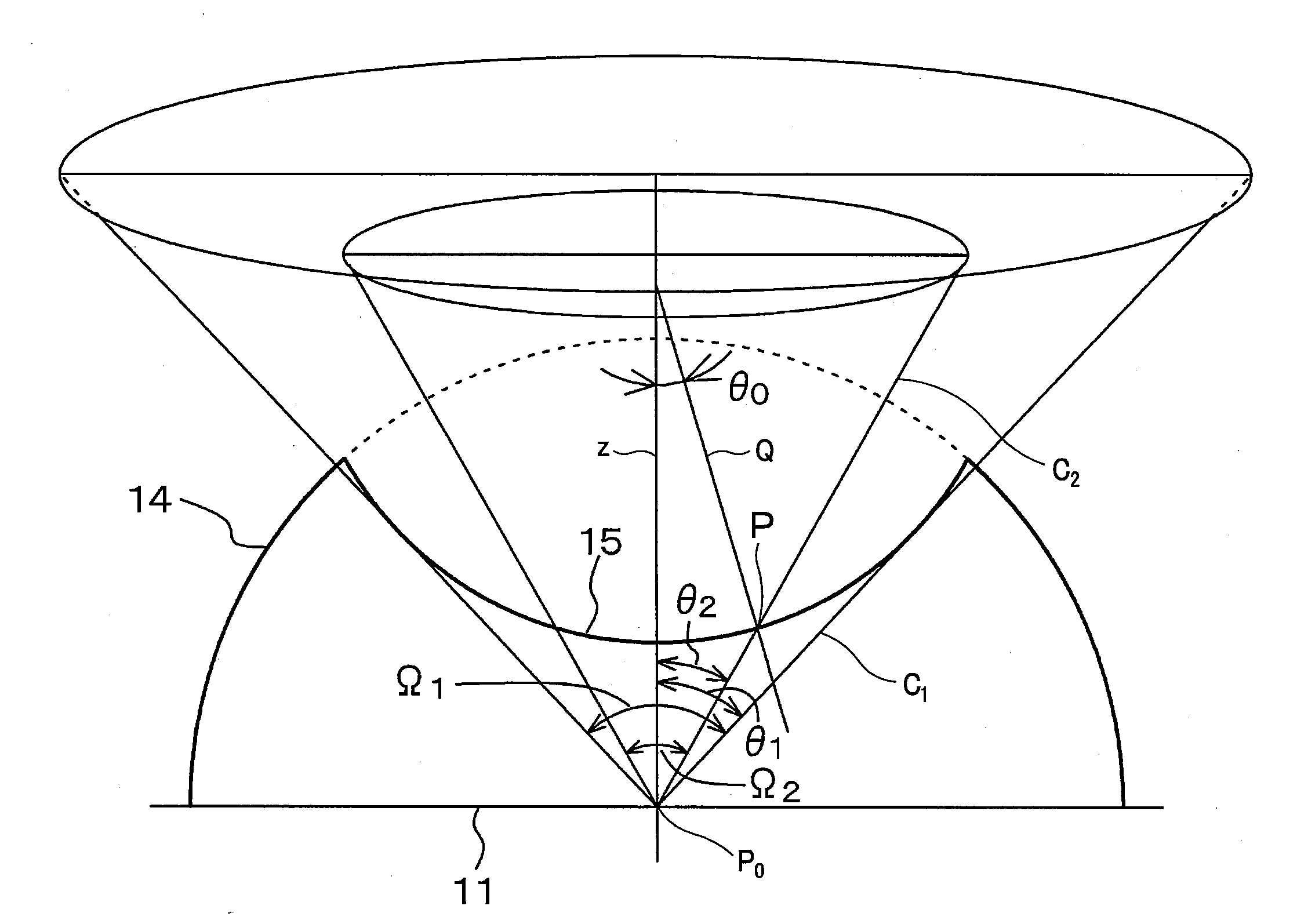
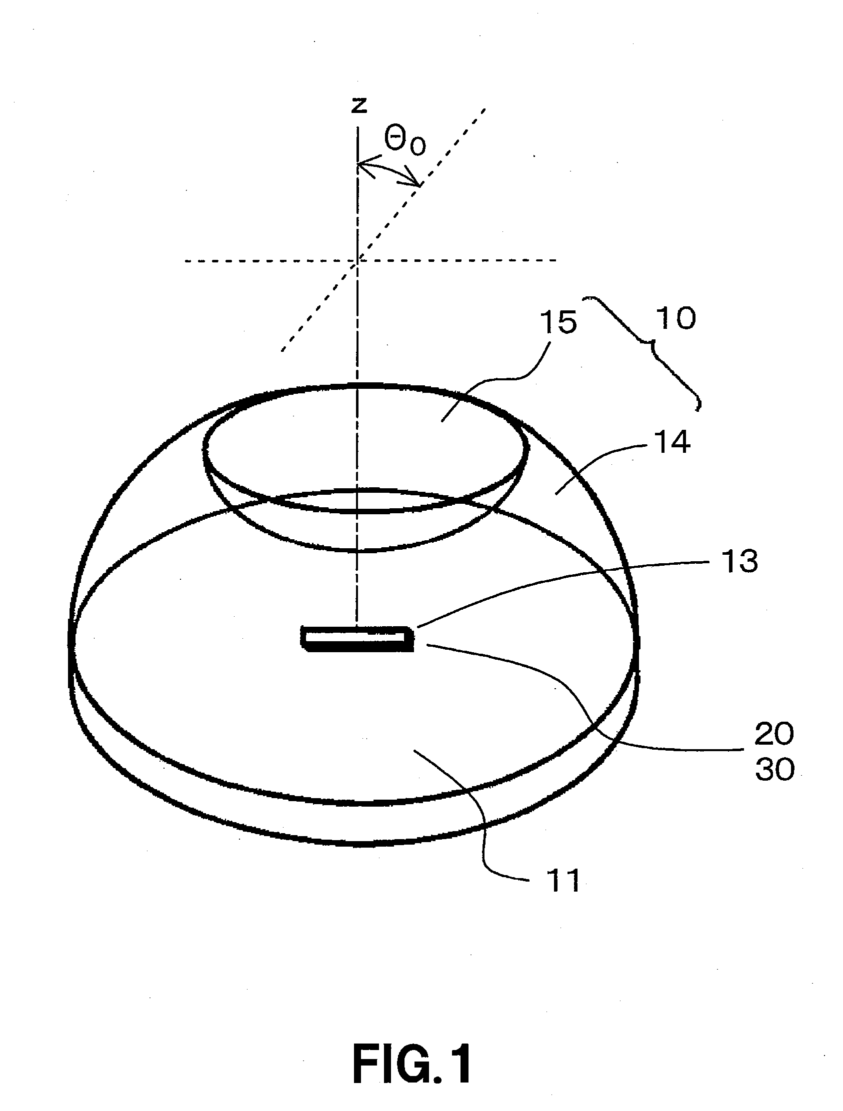
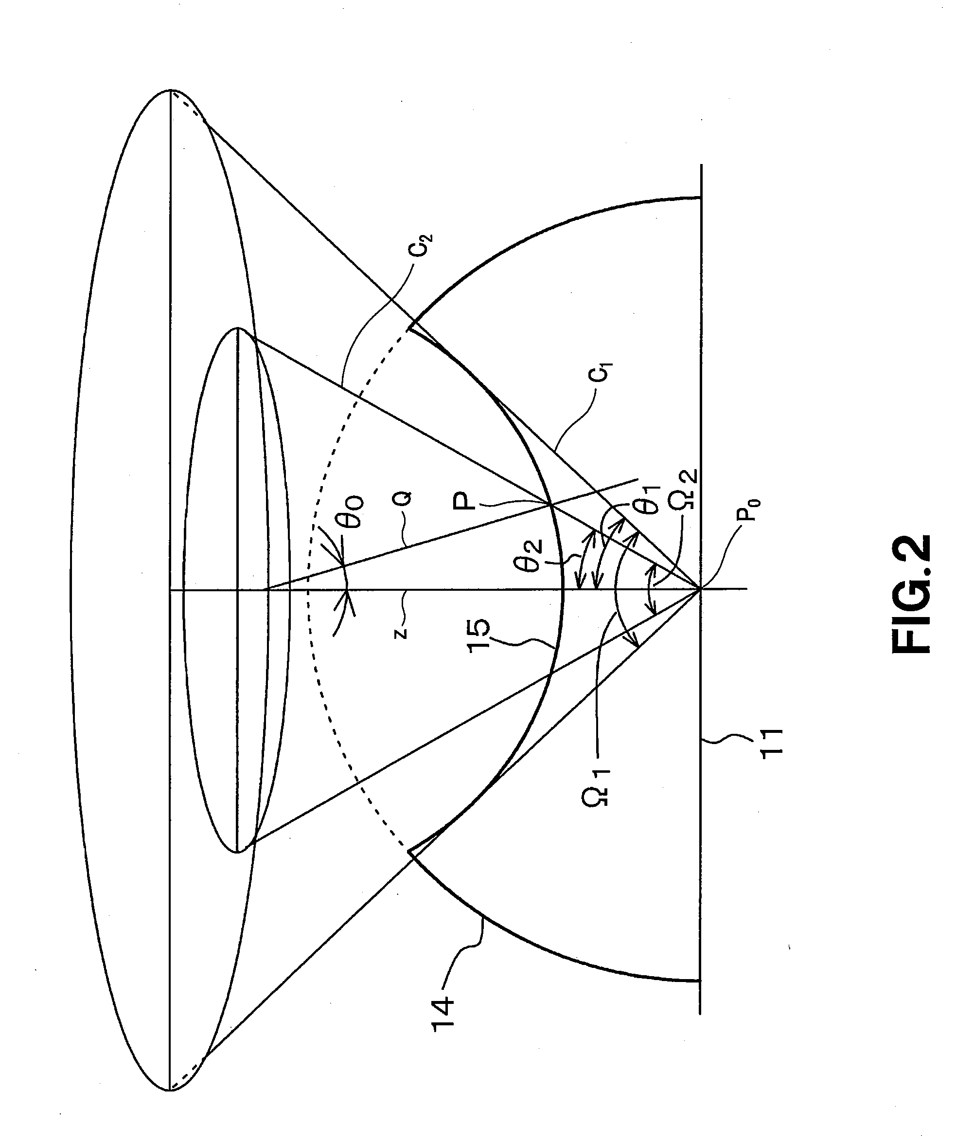
[0084]The Embodiment 1 includes the lenses embodied in the first to third modes of the present invention, light-emitting element assemblies embodied in the first to third modes of the present invention, surface light source devices embodied in the first to third modes of the present invention and color liquid crystal display assemblies embodied in the first to third modes of the present invention. It should be noted that an “apparatus” embodied in any of the first to third modes of the present invention will be referred to as an “apparatus according to Embodiment 1” hereunder. FIG. 1 is a schematic perspective view of the lens according to Embodiment 1, FIG. 2 is a conceptual diagram for explaining the lens according to Embodiment 1, FIG. 3 is a schematic sectional view of the lens according to Embodiment 1, FIGS. 4A, 4B and 6B are schematic sectional views, respectively, of a light-emitting diode, FIGS. 5A, 5B and 6A are conceptual diagrams, respectively, of a light-emitting elemen...

embodiment 2

[0148]Embodiment 2 is a variant of Embodiment 1. In Embodiment 2, the expression (3) defining the lateral face 14 in Embodiment 1 was altered into an expression (10) which will be given below. However, the function fS(z) is the same as that having been explained concerning Embodiment 1 and the coefficients k0 to k4 are same in value as those in Table 1. In Embodiment 2, the value “α” in the expression (10) is given by “0≦α≦0.875”. It should be noted that when α=0, the lateral face 14 is the same as that in Embodiment 1.

r=(1−α)·fS(z)+k′0  (10)

When α is 0, 0.25, 0.50, 0.75, 0.875 or 1.00, the expression (10) is given by “P1(r1, z1)=(1.52, 1.52)”. The value of k′0 was determined for the lateral face 14 given by the expression (10) to intersect with that given by the expression (1). FIG. 23 shows visible outlines of the lateral and top faces, taken along the x-z plane, of the lens. In FIG. 23, a straight line extending vertically from a point where the x-coordinate value is 1.52 indicat...


PUM

PropertyMeasurementUnit
refractive indexaaaaaaaaaa
wavelengthaaaaaaaaaa

Abstract

There is provided a lens formed from a circular bottom face (11), lateral face (14) and top face (15) and having a surface light source (13) of a finite size disposed at the center of the bottom face (11). The top face (15) is an aspheric surface rotational symmetric with respect to a z-axis and which totally reflects a part of a component, whose polar angle is smaller than a polar angle Θ0 at the intersection between the lateral face (14) and top face (15), of light emitted from the surface light source (13). The lateral face (14) is an aspheric surface rotational symmetric with respect to the z-axis and pervious to a component, whose polar angle is larger than the polar angle Θ0, and component, totally reflected at the top face (15), of the light emitted from the surface light source (13). A function r=fS(z) where z is a variable representing the lateral face (14) increases monotonously as the variable z decreases in a closed zone defined by 0≦z≦z1 (z-coordinate of an intersection between the lateral face (14) and top face (15)), and has at least one point where a absolute value |d2r/dz2| is maximum in the closed zone.

Description

TECHNICAL FIELD[0001]The present invention relates to a light-emission lens, light-emitting element assembly including the light-emission lens, surface light source device including the light emitting device, and a color liquid crystal display assembly including the surface light source device.[0002]This application claims the priority of the Japanese Patent Application No. 2004-352027 filed in the Japanese Patent Office on Dec. 3, 2004, Japanese Patent Application No. 2005-133677 filed in the Japanese Patent Office on Apr. 28, 2005 and Japanese Patent Application No. 2005-260908 filed in the Japanese Patent Office on Sep. 8, 2005, the entireties of which are incorporated by reference herein.BACKGROUND ART[0003]As a typical color liquid crystal display assembly, there is well known the color liquid crystal display assembly including a color liquid crystal display in which two panels each formed from a transparent glass substrate having transparent electrodes, alignment layers, etc. ...

Claims


Application Information

Patent Timeline
Patent Type & Authority Applications(United States)
IPC IPC(8): G02F1/13357F21V7/06F21V13/04F21K7/00F21K99/00H01L33/58
CPCG02B5/265H01L33/58G02F1/133603G02B17/0856H01L2224/16225H01L2224/48091H01L2224/73265H01L2924/13091H01L2924/00014H01L2924/00G02F1/1335G02B5/02G02B3/00
Inventor KUBOTA, SHIGEOOSAKO, JUNICHITOMIOKO, SATOSHIUEDA, MITSUNORIYOSHIDA, TETSUYUKINADA, NAOJI
Owner SONY CORP
Why Eureka
Try Eureka