Process and apparatus for synthesis gas and hydrocarbon production

a technology of which is applied in the field of process and apparatus for synthesis gas and hydrocarbon production, can solve the problems of unsatisfactory hsub>2 /sub>to co molar ratio of synthesis gas feed, unsatisfactory aridity, and unsuitable for arid regions, so as to maximize heat recovery, reduce heat loss, and eliminate excess piping

Inactive Publication Date: 2009-11-26
TEXACO INC
View PDF29 Cites 27 Cited by
  • Summary
  • Abstract
  • Description
  • Claims
  • Application Information

AI Technical Summary

Benefits of technology

[0009]According to one aspect, the process and apparatus utilize heat exchangers that thermally integrate the reaction steps such that heat generated by exothermic reactions, e.g., combustion, are arranged closely to the heat sinks, e.g., cool methane, water and air, to minimize heat loss and maximize heat recovery. Effectively, this thermal integration eliminates excess piping throughout, reduces initial capital and operating costs, provides built-in passive temperature control, and improves synthesis gas production efficiencies.
[0010]According to another embodiment, the process is thermally neutral, such that a supplemental fuel, such as methane is no longer needed in order to achieve high reforming efficiency and conversion. This directly translates to lower operating costs.
[0011]According to another aspect, the surface areas and flow configurations of the heat exchangers are designed such that they serve the dual purposes of heat recovery/pre-heating and passive temperature control of process streams. For example, a heat exchanger can preheat a steam and natural gas feed for the reforming reactor with heat derived from a heated reformate while yielding an optimum inlet reformate temperature for the palladium membrane. Also, a heat exchanger can cool the ref

Problems solved by technology

A syngas feed having the desired H2 to CO molar ratio is not readily available and can only be prepared at unacceptably high costs.
One of the biggest challenges in choosing the process is to optimize the energy integration between, the syngas generation and syngas conversion sections.
Use of steam reforming reaction to convert natura

Method used


Image

  • Process and apparatus for synthesis gas and hydrocarbon production
  • Process and apparatus for synthesis gas and hydrocarbon production
  • Process and apparatus for synthesis gas and hydrocarbon production

Examples


Embodiment Construction

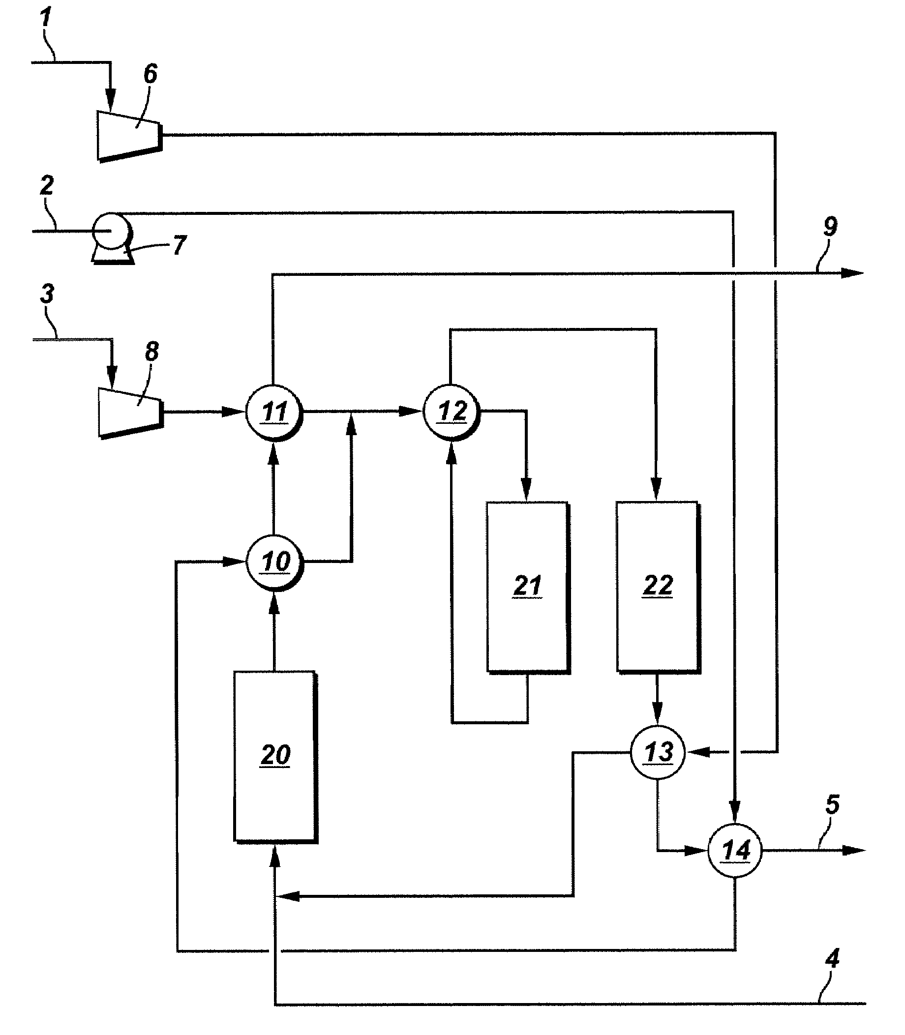
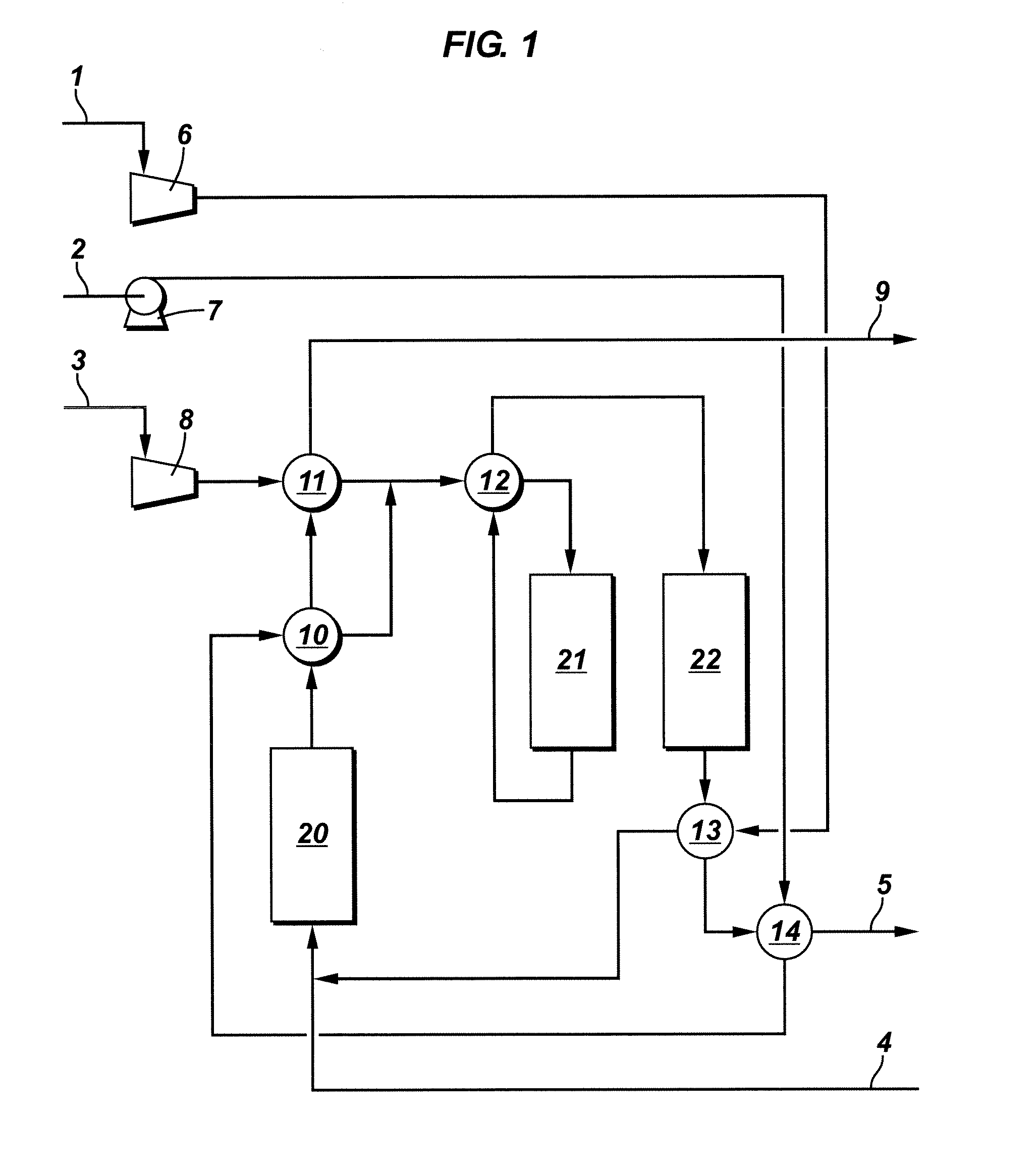
[0037]Provided herein is a process and apparatus to produce a synthesis gas via steam reforming of methane. In the synthesis gas generation process provided herein, methane is converted to synthesis gas comprising carbon monoxide and hydrogen. The process involves steam reformation to produce synthesis gas from methane and water. As used herein, the term “water” generally includes, liquid water, combinations of liquid water and steam, and steam, in one embodiment, the steam reforming reaction is thermally integrated with a catalytic combustion to improve thermal efficiency and synthesis gas production.

[0038]Steam methane reforming (“SMR”) comprises an endothermic reaction requiring 57 kW of heat and proceeds according to the following equation:

CH4+H2O→CO+3H2

[0039]In one embodiment, the SMR reaction takes place in presence of a steam reforming catalyst. Any SMR catalyst known to one of skilled in the art could be used. Exemplary SMR catalysts include, but are not limited to rhodium,...


PUM

PropertyMeasurementUnit
Temperatureaaaaaaaaaa

Abstract

A process and apparatus for preparing a synthesis gas suitable for feeding to a suitable hydrocarbon production reactor, such as a Fischer Tropsch reactor is described. According to one aspect, the process and apparatus utilize heat exchangers that thermally integrate the reaction steps such that heat generated by exothermic reactions, e.g., combustion, are arranged closely to the heat sinks, e.g., cool methane, water and air, to minimize heat loss and maximize heat recovery. Effectively, this thermal integration eliminates excess piping throughout, reduces initial capital and operating costs, provides built-in passive temperature control, and improves synthesis gas production efficiencies.

Description

FIELD[0001]Provided herein is a process for preparation of a synthesis gas and an apparatus having a catalytic oxidizer and a reforming reactor and optionally a palladium membrane integrated in a single vessel assembly.DESCRIPTION OF THE RELATED ART [0002]Mixtures of hydrogen and carbon monoxide are often referred to as synthesis gas. Such synthesis gas can be used in numerous well-known processes to produce a large variety of organic compounds, such as production of methanol, and other compounds containing carbon, hydrogen and, optionally, oxygen moieties. One such process for the preparation of paraffinic hydrocarbons from a mixture of carbon monoxide and hydrogen (syngas) is Fischer-Tropsch synthesis. This synthesis process involves contacting syngas at elevated temperature and pressure with a Fischer Tropsch catalyst to yield paraffinic hydrocarbons.[0003]The Fischer-Tropsch synthesis process typically consumes syngas at a H2 to CO molar usage ratio of 2:1 to 3:1, depending on t...

Claims


Application Information

Patent Timeline
IPC IPC(8): C07C1/04C01B3/26B01J19/00
CPCB01J8/0214C01B2203/1695B01J8/0285B01J12/007B01J19/2485B01J2208/00203B01J2208/00212B01J2208/00309B01J2208/0053B01J2219/00083B01J2219/00085B01J2219/00117B01J2219/00159C01B3/384C01B3/505C01B2203/0233C01B2203/0405C01B2203/047C01B2203/062C01B2203/0811C01B2203/0883C01B2203/1011C01B2203/1023C01B2203/1035C01B2203/1058C01B2203/1241C01B2203/1294C01B2203/169B01J8/0278Y02P20/10Y02P20/129
Inventor CASEY, DANIEL GLENNYOU, LIXINKRAUSE, CURTIS LEENGUYEN, KEVIN HOA
Owner TEXACO INC
Why Eureka
Try Eureka