Light source device, imaging apparatus and endoscope apparatus

a light source and imaging technology, applied in the field of light source devices, imaging apparatuses and endoscope apparatuses, can solve the problems of poor color rendering properties, short intensity of light, and inability to obtain observation images peculiar to specific wavelength bands, and achieve high precision

Inactive Publication Date: 2009-12-17
FUJIFILM CORP
View PDF32 Cites 59 Cited by
  • Summary
  • Abstract
  • Description
  • Claims
  • Application Information

AI Technical Summary

Benefits of technology

[0025]Furthermore, according to the endoscope apparatus of any of the above configurations, good observation images can be captured under plural types of illumination light, and thus it is possible to make the special light diagnosis with high precision.

Problems solved by technology

However, in this case, the illumination light runs short of an intensity of light around 450 to 480 nm and thus is poor in color rendering property as compared to a continuous spectrum, over a wavelength 430 to 680 nm, of an illumination light (Xe lamp), of the related art, for an endoscope.
However, as shown in FIG. 12B, under the illumination with in the special light, when the light in the specific wavelength band is light having a wavelength within the excitation wavelength band W, unnecessary fluorescence is emitted from the phosphor, and thus an observation image peculiar to the specific wavelength band might not be obtained.

Method used


Image

  • Light source device, imaging apparatus and endoscope apparatus
  • Light source device, imaging apparatus and endoscope apparatus
  • Light source device, imaging apparatus and endoscope apparatus

Examples


first embodiment

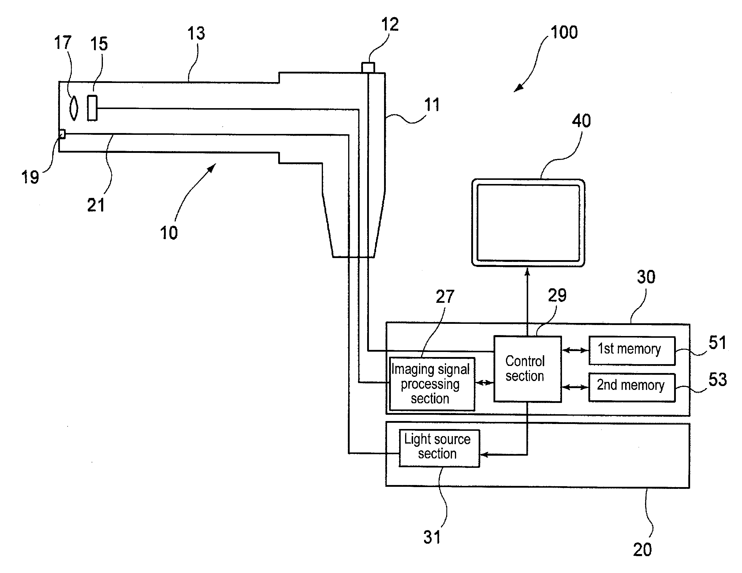
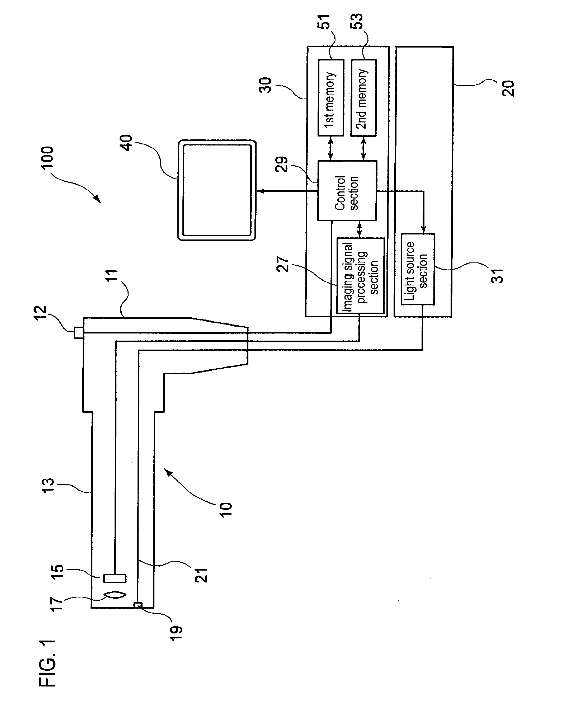
[0039]FIG. 1 is a conceptual configuration view showing an endoscope apparatus of this embodiment.

[0040]An endoscope apparatus 100 of this embodiment is configured to mainly include an endoscope 10, a light source device 20, an image processing device 30, and a monitor 40.

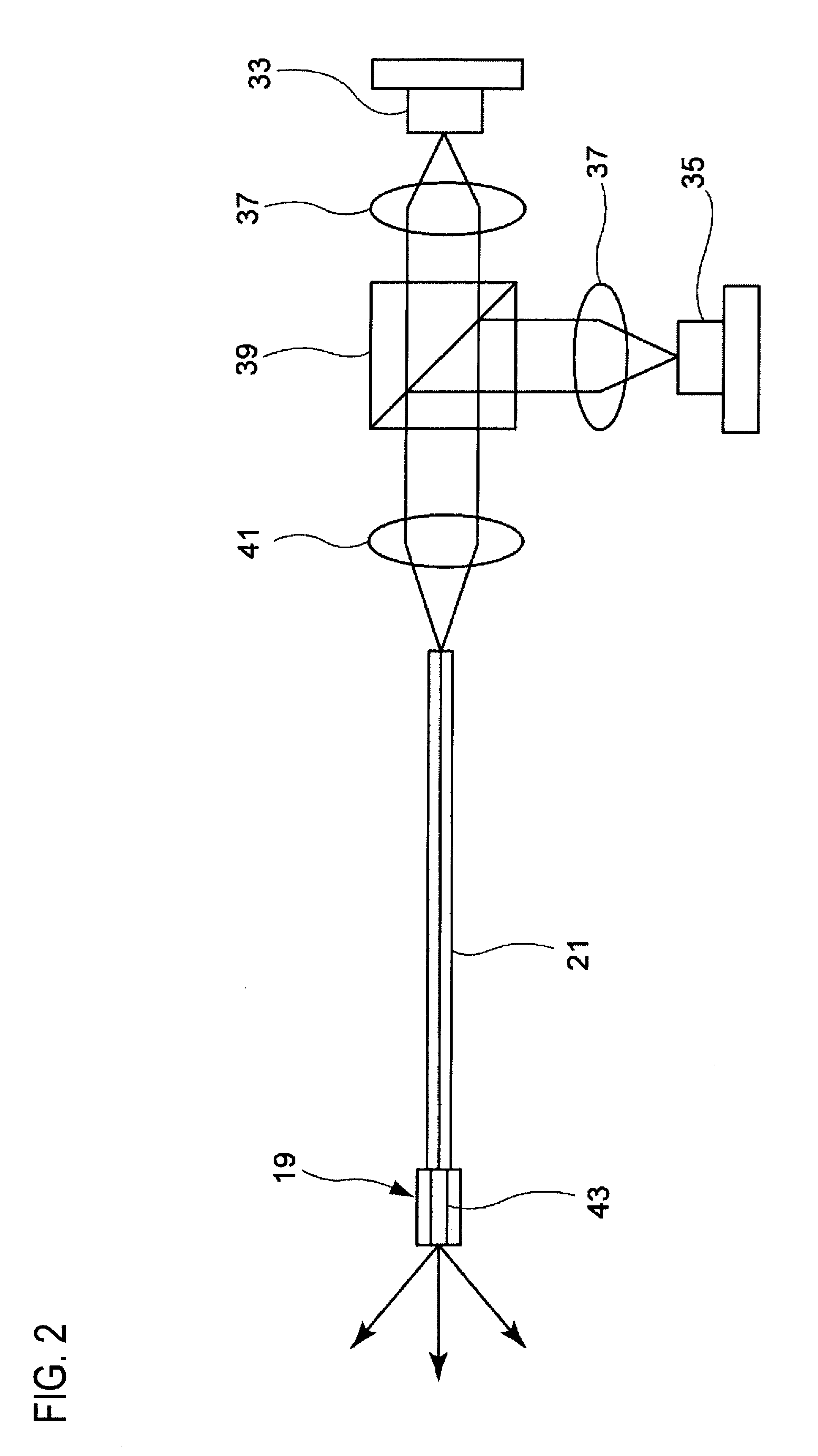
[0041]The endoscope 10 has a main body operation portion 11, and an endoscope insertion portion 13 that is connected to the main body operation portion 11 and is inserted into an object to be inspected (body cavity). An imaging element 15 and an imaging lens 17 which serve as an imaging optical system are disposed at the front end portion of the endoscope insertion portion 13. Also, an illumination optical member 19 of an illumination optical system and an optical fiber 21 connected to the illumination optical member 19 are disposed in vicinity of the imaging optical system. The optical fiber 21 is connected to a light source section 31 of the light source device 20 (which will be described in detail later), and an...

second embodiment

[0069]Next, a light source device according to another embodiment will be described below.

[0070]FIG. 5 is a configuration view showing another optical system of the light source device shown in FIG. 1. Here, the same reference symbols are affixed to the same members as those shown in FIG. 2, and explanation thereon will be omitted or simplified.

[0071]This embodiment is configured so that the optical system shown in FIG. 2 can emit a green laser beam. That is, as shown in FIG. 5, a dichroic prism 47 for introducing a green laser beam is disposed in front of the emission optical path of the dichroic prism 39 for introducing the blue laser emitted from the blue laser light source 35. A green laser beam emitted from a green laser light source 49 is introduced into this dichroic prism 47 via the collimator lens 37.

[0072]As the green laser light source 49, a YAG-SHG laser whose center wavelength is 532 nm may be used.

[0073]The green laser beam from the green laser light source 49 is coupl...

third embodiment

[0076]Next, a third embodiment that is configured so that the spectral characteristic of the imaging element is correlated with the light source wavelength of the illumination optical system will be described below.

[0077]The light source of this embodiment has basically the similar configuration to that in the first embodiment, but a relationship between the imaging element and the light source that excites the phosphor is defined in this embodiment.

[0078]The imaging element 15 of this embodiment (see FIG. 1) has R (red), G (green), and B (blue) detection spectral characteristics as shown in FIG. 7. In this case, the spectral sensitivity for blue that is the detection color on the shortest wavelength side is set not to include the emission wavelength λ1 of the near-ultraviolet laser light source. As a result, the light emitted from the near-ultraviolet laser light source, which excites the phosphor 43 to emit light, is not detected by the imaging element 15.

[0079]That is, the emissi...


PUM


Abstract

A light source device includes a first light source 33, a second light source 35 having an emission wavelength that is different from the first light source 33, and a phosphor 43 that is disposed to be distant from the first light source 33 and the second light source 35 and absorbs light in a predetermined excitation wavelength band to emit fluorescence. The phosphor 43 is disposed on an emission light optical path that is shared by the first light source 33 and the second light source 35. The emission wavelength of the first light source 33 is in the predetermined excitation wavelength band. The emission wavelength of the second light source 35 is outside of the predetermined excitation wavelength band.

Description

CROSS-REFERENCE TO RELATED APPLICATIONS[0001]This application claims the benefit of Japanese Patent Application No. 2008-156032, filed Jun. 13, 2008, the entire contents of which are hereby incorporated by reference, the same as if set forth at length.BACKGROUND OF THE INVENTION[0002]1. Technical Field[0003]The invention relates to a light source device, an imaging apparatus and an endoscope apparatus.[0004]2. Description of the Related Art[0005]An endoscope apparatus that has been widely used is configured so that illumination light from a lamp that is provided in a light source device is guided by a light guide that is provided along an endoscope insertion portion, and the illumination light guided by this light guide is emitted from an illumination window that is provided at a front end of the endoscope insertion portion so as to illuminate an object site to be inspected. On the other hand, JP 2005-205195 A describes a light source device in which a blue laser beam is guided to a...

Claims


Application Information

Patent Timeline
Patent Type & Authority Applications(United States)
IPC IPC(8): A61B1/06F21V9/16G02B6/02H04N5/225
CPCA61B1/05A61B1/0638A61B1/0653A61B1/07A61B1/0661A61B5/0084A61B5/0086A61B1/063A61B1/06A61B5/0071A61B1/0655
Inventor SUNAGAWA, HIROSHIMIZUYOSHI, AKIRA
Owner FUJIFILM CORP
Why Eureka
Try Eureka