Extreme ultra violet light source apparatus

a light source and ultra violet technology, applied in the field of extreme ultraviolet light source apparatus, can solve the problems of reducing the accuracy of patterning, poor output efficiency of euv light, and easy breakage of thin films, so as to reduce the risk of deformation and breakage caused by the temperature rise of the spf. , the effect of high spectrum purity

Active Publication Date: 2009-12-24
GIGAPHOTON
View PDF14 Cites 84 Cited by
  • Summary
  • Abstract
  • Description
  • Claims
  • Application Information

AI Technical Summary

Benefits of technology

[0017]According to the one aspect of the present invention, by using the spectrum purity filter (SPF) including the mesh formed with an arrangement of apertures having a pitch not larger than a half of a shortest wavelength of the laser beam applied by the driver laser, the EUV light having a short wavelength is transmitted and the CO2 laser beam having a long wavelength is reflected

Problems solved by technology

Further, infrared light contained in the excitation laser beam may be absorbed by optical parts, masks, wafers, and so on, to cause thermal expansion, and it may reduce the accuracy of patterning.
Accordingly, in view of removal of the CO2 laser beam, there have been the following problems in the above-mentioned conventional technologies.
(1) Since the transmittance of the thin film filter type SPF that isolates the exposure unit from the EUV light source apparatus is as low as about 40%, the output efficiency of EUV light is very poor.
Further, the thin film is easily broken by the incidence of debris.
Furthermore, when debris adheres to the thin film, the debris absorbs EUV light a

Method used


Image

  • Extreme ultra violet light source apparatus
  • Extreme ultra violet light source apparatus
  • Extreme ultra violet light source apparatus

Examples


first embodiment

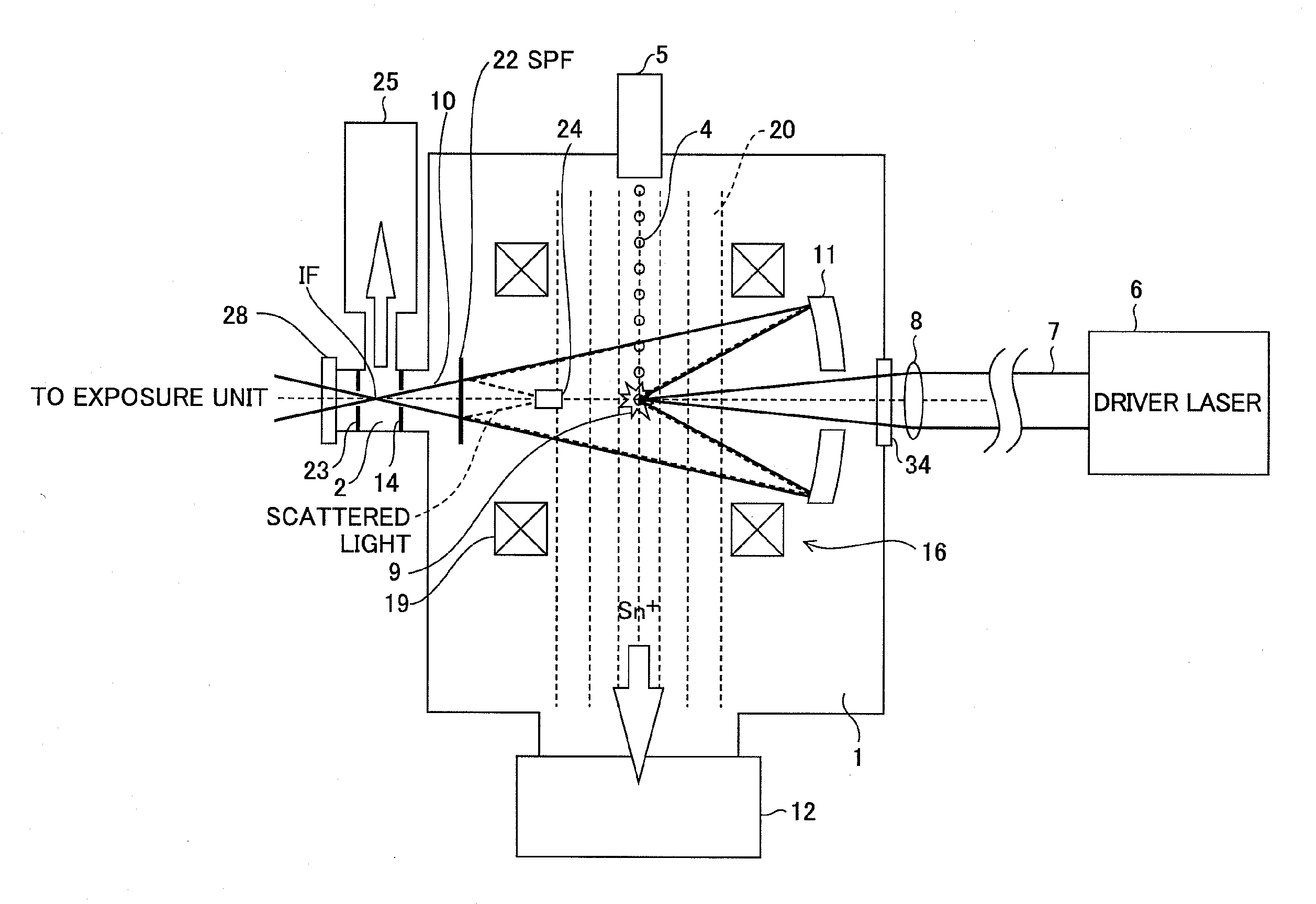
[0037]FIG. 1 shows a configuration of an extreme ultraviolet (EUV) light source apparatus according to the first embodiment of the present invention. The EUV light source apparatus employs a laser produced plasma (LPP) type of generating EUV light by applying a laser beam to a target material for excitation.

[0038]As shown in FIG. 1, the EUV light source apparatus according to the embodiment includes a first vacuum chamber 1 in which EUV light is generated and a second vacuum chamber 2 for guiding the generated EUV light to an external exposure unit, and improves the quality of the generated EUV light 10 with a mesh-type spectrum purity filter (SPF) 22.

[0039]Further, the EUV light source apparatus includes a target supply unit 5 for supplying a target 4 to a predetermined position (beam focusing point 9) within the first vacuum chamber 1, a driver laser 6 provided outside of the first vacuum chamber 1, a laser beam focusing optics 8 including at least one lens and / or at least one mir...

second embodiment

[0077]FIG. 11 shows a configuration of an extreme ultraviolet light source apparatus according to the second embodiment of the present invention. In the second embodiment, a driver laser 32 uses a laser gas containing a carbon dioxide (CO2) gas as a laser medium and radiates an excitation laser beam (CO2 laser beam) having linear polarization, and a wire grid polarizer is used in place of the mesh in a spectrum purity filter (SPF) 33. The rest of the configuration is the same as that in the first embodiment.

[0078]FIG. 12 is a principle diagram for explanation of the polarization direction of the CO2 laser beam and the wire grid polarizer. The wire grid polarizer 41 has periodically arranged wires of a metal or the like, and the wire spacing is made equal to or less than a half of a wavelength of an incident electromagnetic waves, that is, the CO2 laser beam in the embodiment.

[0079]As shown in FIG. 12, the wire grid polarizer 41 has transmittance that changes according to the polariz...

third embodiment

[0088]FIG. 13 shows a configuration of an extreme ultraviolet light source apparatus according to the third embodiment of the present invention. In the embodiment, an SPF of gas absorption type specialized for blocking the CO2 laser beam is used and sulfur hexafluoride (SF6) gas is used as a gas for absorption. The rest of the configuration is the same as that in the first embodiment.

[0089]In the embodiment, a gas introducing nozzle 43 and a gas discharging nozzle 47 are provided to face each other near the IF within the first vacuum chamber 1. The SF6 gas is introduced near the IF within the first vacuum chamber 1 via the gas introducing nozzle 43 and the SF6 gas is collected into the gas discharging nozzle 47 by using a vacuum evacuation pump, and thereby, a gas curtain 45 of SF6 is generated. The sulfur hexafluoride (SF6) gas has a property of specifically absorbing the CO2 laser beam having a wavelength of 10.6 μm, and absorbs and blocks the CO2 laser beam of the light focused t...


PUM


Abstract

An extreme ultraviolet light source apparatus using a spectrum purity filter capable of obtaining EUV light with high spectrum purity. The apparatus includes a chamber; a target supply unit for supplying a target material; a driver laser using a laser gas containing a carbon dioxide gas as a laser medium, for applying a laser beam to the target material to generate plasma; a collector mirror for collecting and outputting the extreme ultraviolet light radiated from the plasma; and a spectrum purity filter provided in an optical path of the extreme ultraviolet light, for transmitting the extreme ultraviolet light and reflecting the laser beam, the spectrum purity filter including a mesh having electrical conductivity and formed with an arrangement of apertures having a pitch not larger than a half of a shortest wavelength of the laser beam applied by the driver laser.

Description

CROSS-REFERENCE TO RELATED APPLICATION[0001]The present application claims priority from Japanese Patent Application No. 2008-154012 filed on Jun. 12, 2008, the contents of which are incorporated herein by reference in their entirety.BACKGROUND OF THE INVENTION[0002]1. Field of the Invention[0003]The present invention relates to an extreme ultraviolet (EUV) light source apparatus for generating extreme ultraviolet light by applying a laser beam to a target material to turn the target material into plasma, and specifically, to an EUV light source apparatus for supplying high-quality extreme ultraviolet light with spectrum purity improved by eliminating the influence of the laser beam applied to the target material.[0004]2. Description of a Related Art[0005]Recent years, as semiconductor processes become finer, photolithography has been making rapid progress to finer fabrication. In the next generation, microfabrication at 70 nm through 45 nm, further, microfabrication at 32 nm and be...

Claims


Application Information

Patent Timeline
IPC IPC(8): G21K5/00
CPCG03F7/70191G03F7/70575G03F7/70858H05G2/005G21K1/10H05G2/008G21K5/04G03F7/70941
Inventor MORIYA, MASATOWAKABAYSHI, OSAMUABE, TAMOTSUSUGANUMA, TAKASHIENDO, AKIRASUMITANI, AKIRA
Owner GIGAPHOTON
Why Eureka
Try Eureka