Material for contact components or battery components, and battery using the same

a technology of contact components and battery components, which is applied in the direction of cell components, liquid/solution decomposition chemical coatings, non-aqueous electrolyte cells, etc., can solve the problems of increasing equipment costs, labor costs, energy consumption, and the like, and achieves low cost, stable effect, and low surface resistance valu

Inactive Publication Date: 2009-12-31
PANASONIC CORP +1
View PDF3 Cites 3 Cited by
  • Summary
  • Abstract
  • Description
  • Claims
  • Application Information

AI Technical Summary

Benefits of technology

[0026]According to the present invention, a material for contact components or battery components which can stably maintain a low surface resistance value for a long period of time can be provided at a low cost. The material for contact components or battery components of the present invention has a surface resistance value, which is same as or less than the conventional ones, as well as corrosion resistance, workability, solderability, and the like, which are same as or greater than the conventional ones, and even in the case of storage in a constant-temperature constant-humidity chamber, the increase in the surface resistance value is small.

Problems solved by technology

However, the process of applying the carbon paste is cumbersome, and a large encumbrance is required for drying the carbon paste.
For this reason, equipment costs, labor costs, energy consumption, and the like increase, and it is difficult to attempt reduction in production costs.

Method used


Image

  • Material for contact components or battery components, and battery using the same
  • Material for contact components or battery components, and battery using the same
  • Material for contact components or battery components, and battery using the same

Examples


example 1

(i) Metal Sheet

[0072]On the premise that Fe, as a first metal element, was eluted into the treatment solution, a stainless steel plate (SUS430) was used for a metal sheet. A cathodic electrolytic degreasing of the stainless steel plate was performed, and subsequently, pretreatment was performed, in which the stainless steel plate was immersed in a hydrochloric acid aqueous solution (HCl concentration of 35 wt %, pH 1 or less) of 30° C. for 1 minute. Meanwhile, for the “Hydrochloric Acid Immersion” column in Tables 1 to 2, a “◯” is indicated for the case where immersion using hydrochloric acid aqueous solution was performed, and a “×” for the case where the immersion was not performed.

(ii) Preparation of Treatment Solution

[0073]Treatment solutions having various compositions, as shown in Tables 1 to 2, were prepared.

[0074]For a water-soluble metal salt containing a second metal element, indium sulfate, silver nitrate, palladium chloride, and chlorauric acid were used alone, or by com...

example 2

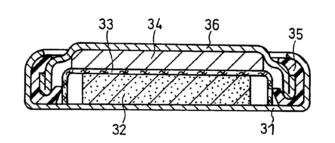
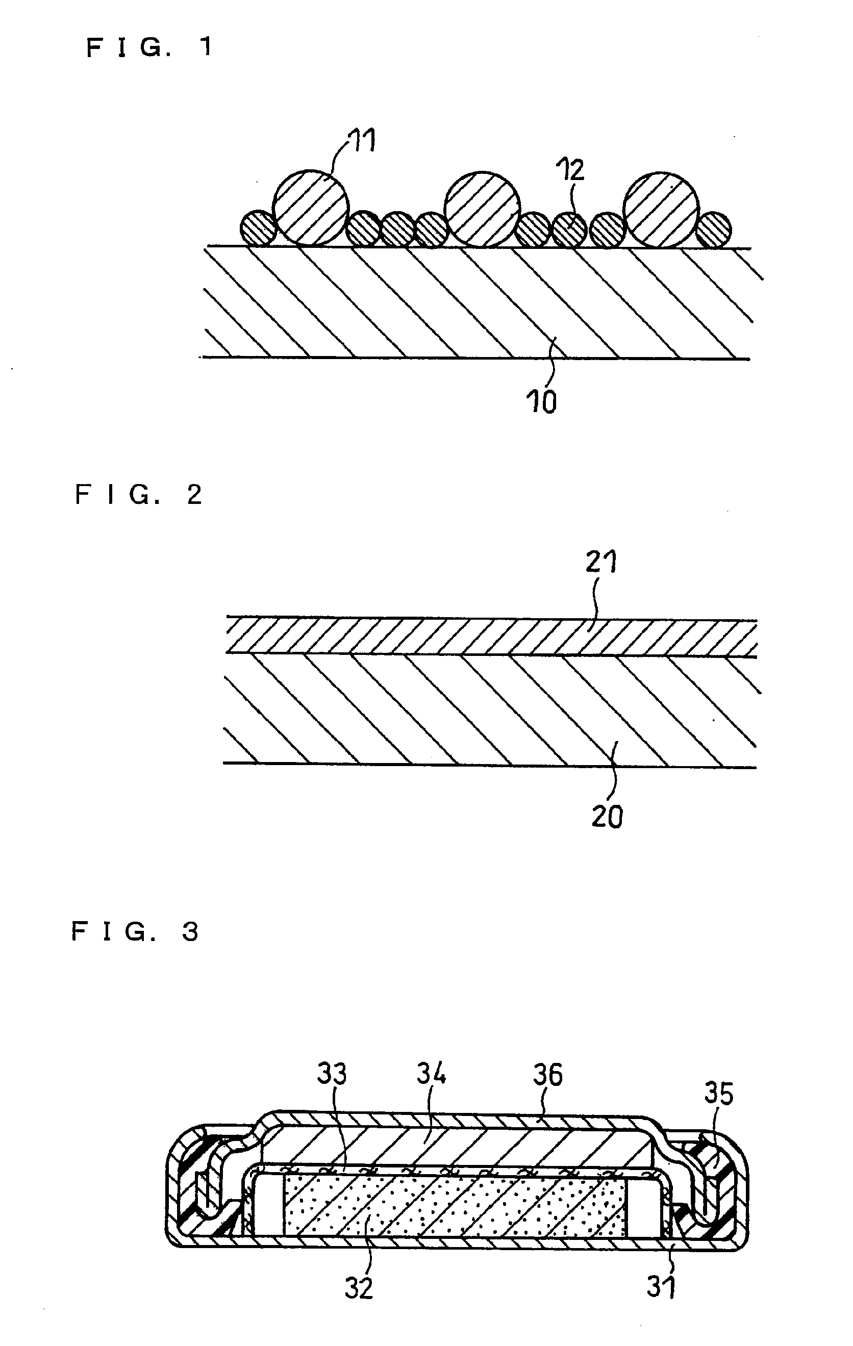
[0084]A coin-type lithium primary battery, having a structure as shown in FIG. 3, was fabricated by using the positive electrode case fabricated in Examples 1-8.

(i) Fabrication of Positive Electrode

[0085]A positive electrode was fabricated, similar to the one fabricated at the time of determining the initial contact resistance value. That is, to 100 parts by weight of manganese dioxide, were added 5 parts by weight of Ketjen Black as a conductive material and 5 parts by weight of polytetrafluoroethylene (PTFE) as a binder, and then sufficiently mixed to obtain a positive electrode mixture. This positive electrode mixture was formed into a disc shape having a diameter of 20 mm and a thickness of 3.0 mm, then dried at 250° C., and the resultant was referred as the positive electrode.

(ii) Fabrication of Negative Electrode

[0086]A disc shape having a diameter of 20 mm was punched out of a metallic lithium having a thickness of 1.0 mm, and this was used as a negative electrode.

(iii) Prepa...


PUM

PropertyMeasurementUnit
humidityaaaaaaaaaa
temperatureaaaaaaaaaa
humidityaaaaaaaaaa

Abstract

A material for contact components or battery components, which includes a metal sheet having a surface layer portion containing a first metal element, the metal sheet including a Cr-containing steel plate or a surface-treated steel plate, and at least a part of the first metal element on an outermost surface of the surface layer portion being substituted by a second metal element having a nobler standard electrode potential than the first metal element, the second metal element being deposited on the outermost surface in a state of a particulate metal, oxide, or hydroxide.

Description

TECHNICAL FIELD [0001]The present invention mainly relates to a material for contact components or battery components, which can stably maintain a low surface resistance value for a long period of time.BACKGROUND ART [0002]For the material for contact components or battery components, steel plates (including steel strips) such as Cr-containing steel plate, surface-treated steel plate, and the like are widely used. For use intended for contact components, contact resistance value, solderability, and the like are considered important. For use intended for battery components, corrosion resistance, workability, and the like are considered important. In general, as the steel plate intended for use for contact components, various types of surface-treated steel plates (e.g., nickel-plated steel plate, tin-plated steel plate, or copper-plated steel plate) and the like are used, from the perspective of obtaining low contact resistance value and good solderability. On the other hand, as the s...

Claims


Application Information

Patent Timeline
Patent Type & Authority Applications(United States)
IPC IPC(8): H01M4/38B32B15/18B32B15/16B05D5/12H01M50/128
CPCH01M6/16C23C18/54H01M2/0275H01M2/027C23C18/42H01M2/0285Y10T428/1209H01M10/052C23C18/32Y10T428/12063C23C18/38H01M4/661Y10T428/12972Y02E60/10H01M50/545H01M50/128
Inventor OKANO, TAKUYUKIIKEHATA, TOSHIHIKOIGUCHI, MISAOHAYASHI, KEIICHI
Owner PANASONIC CORP
Why Eureka
Try Eureka