Method for producing heterogeneous composites

a composite material and polymer technology, applied in the direction of non-metal conductors, instruments, conductors, etc., can solve the problems of limiting factors, undesirable sacrifices, and the need for fillers, and achieve enhanced properties, reduced bulk filler concentration, and high thermal and/or electrical conductivity.

Inactive Publication Date: 2010-01-07
LORD CORP
View PDF20 Cites 27 Cited by
  • Summary
  • Abstract
  • Description
  • Claims
  • Application Information

AI Technical Summary

Benefits of technology

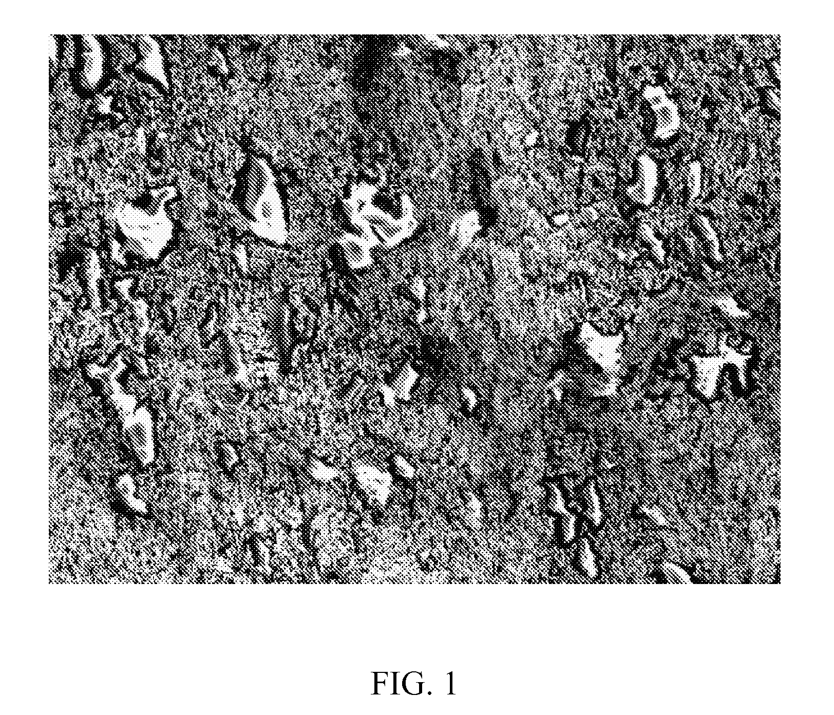
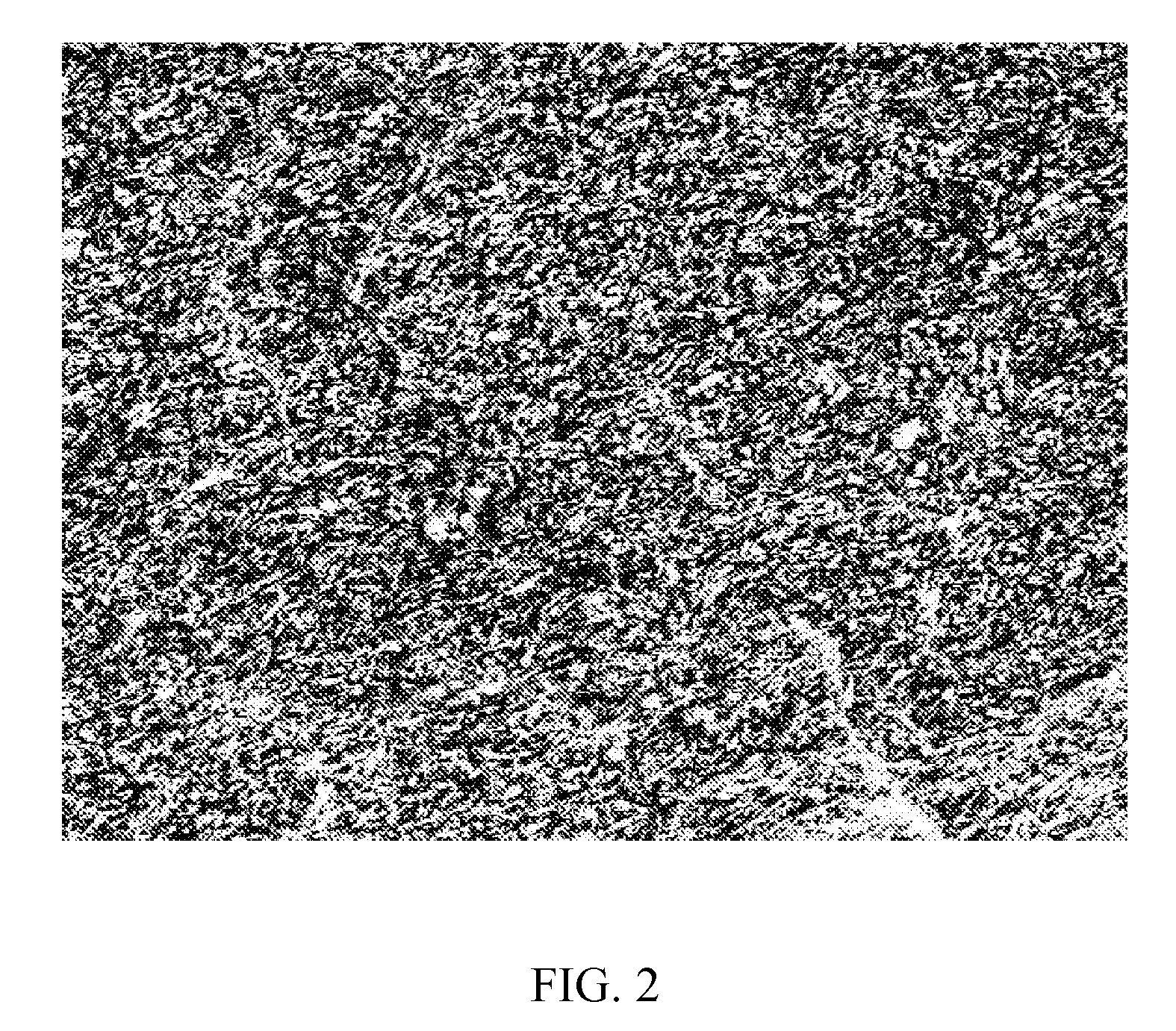
[0011]This invention describes a method for selecting materials and processing conditions to prepare a heterogeneous structure in situ via the reaction of a homogeneous mixture of a reactive organic compound and a filler, which may then optionally be sintered. In a preferred embodiment of the present invention, the method is employed to provide a heterogeneous composite possessing exceptionally high thermal and / or electrically conductivities for a given concentration of conductive filler. The choice of materials as well as processing conditions employed, as will be described below, have a strong effect on the rate domain formation / heterogeneity of the structure formed, the extent of filler particle-particle interactions within filler-rich domains, and ultimately the thermal and / or electrical conductivity. Proper choice of these conditions can lead to composites having enhanced properties at a reduced bulk filler concentration.
[0012]One aspect of the present invention is lower electrical percolation threshold concentrations and enhanced conductivities beyond percolation can be achieved through the formation of a heterogeneous composite from the reaction of a homogeneous mixture of filler and organic compound. Through appropriate selection and reaction of the organic compound, a heterogeneous structure can be formed comprising filler rich domains that are greater in concentration that of the bulk filler concentration. Such a structure, as will be shown, ultimately allows for electrically percolation to occur at significantly lower concentrations of filler than what is required in final composites that comprise a homogeneous dispersion of filler. Moreover, the structure when formed from sinterable or metal fillers and cured under the appropriate conditions is capable of forming a fused network of filler thereby further improving electrical conductivity at levels.
[0020]In a still further aspect of the present invention, a method for increasing the conductivity of a conductive composition is provided comprising, selecting an inorganic filler which is at least one of thermally conductive and electrically conductive, selecting an organic material, selecting a desired filler amount, mixing the conductive filler and organic material, wherein the homogeneous mixture of filler and matrix material comprises a bulk conductivity, and selecting cure conditions to create a heterogeneous structure so as to provide a cured composition comprising a conductivity that is higher than the bulk conductivity of the mixture having a homogeneous structure.
[0021]In an additional aspect of the present invention, a thermally conductive adhesive is provided comprising, a filler coated with a non-polar coating, an organic component comprising polar functionality, and wherein the thermal conductivity of the cured adhesive is greater than 15 W / mK and the silver flake concentration is less than 50% by volume. Unlike other methods for producing filled polymeric systems, the methods of embodiments of the present invention provide higher thermal and / or electrical conductivity at significantly lower filler contents. This typically leads to lower viscosities, better toughness, better adhesion, and other enhanced physical properties all while achieving higher conductivities that bulk filler loading would allow.
[0022]Additionally, the lower concentration of filler permits less adsorbed moisture and air in the formulation brought in by the filler allows for better wetting of a substrate, and enables for application methods such as screen printing due to the newly achieved low-viscosity 100% solids system, which provides the same or better conductivity as prior art systems.

Problems solved by technology

In many instances the level of filler required leads to undesirable sacrifices in other important physical characteristics of the composite, such as dispense viscosity, adhesion, impact strength, among other things.
In some instances, the cost of the filler is a limiting factor, particular for such fillers as gold, silver, or carbon fibers.
In many instances, undesirable increases in viscosity occur to the point handling (or dispensing) becomes an issue which often limits the thermal conductivity that can be achieved.
However, a downside to this approach, as seen in epoxy based formulations, is these low molecular weight species cause shrinkage issues, void formation, and delamination when the adhesive is cured.
While highly thermally conductive, this material is quite limited in its ability to adhere to surfaces and has an intrinsically high modulus owing to pure filler remaining once the solvent is removed.
Moreover, most packaging processes prefer low solver to solvent-less materials owing to the complexities and environment concerns with removing solvent.
Unfortunately, sintering in not achieved at low to moderate fillers loadings.
This limitation is associated with the lack of direct filler particle contacts required for filler to occur due to the matrix material that coats them.
It is only at very high volume percent filler that some sintering occurs, but at such concentrations the unreacted adhesive composition becomes extremely viscous and even solid-like and lacks the desirable polymeric attributes such as good adhesion, toughness, etc.

Method used


Image

  • Method for producing heterogeneous composites
  • Method for producing heterogeneous composites
  • Method for producing heterogeneous composites

Examples


example 1

[0052]Silver flake coated with stearic acid was first added to a reactive organic resin, namely diglycidal either of bisphenol F (DGEBF), in a 100 gram Hauschild® mixing cup and thoroughly mixed for a minimum of two cycles at 2200 rpm for 1 minute / cycle. A second reactive organic compound, i.e. a curing agent, was then added and mixed for a minimum of two cycles at 2200 rpm for 1 minute / cycle. The resulting material was cast between 19 mm thick, Teflon coated aluminum plates separated with 1 mm glass slides. Samples were cured with a convection oven using a programmed ramp which consisted of heating the sample from room temperature to 160° C. over the course of 40 minutes followed by an isothermal hold for 1 hour.

[0053]Bulk thermal conductivity was measured via the Flash Method (ASTM E1461). Test specimens were cut from the cured samples. Samples were 12.7 mm in diameter and ˜1 mm in thickness. All samples were spray-coated with a thin film of graphite to ensure complete absorption ...

example 2

[0061]The samples corresponding to data shown in Table 2 and FIGS. 4-6 were prepared according the description provided in Example 1 with the exceptions of select electrical volume conductivity measurements. The resistance (or conductance) of each sample dictated the choice of resistivity instrumentation. Samples having resistances in excess of ˜1010 ohms were measured via ASTM D-257 using a HP 4339B High Resistance Meter equipped with a 16008B resistance cell. Samples were in the form of circular disks ˜1 mm in thickness and >60 mm in diameter. Samples having resistances in the range of ˜102-1010 ohms were measured using a Keithley 610C Electrometer. Samples in this case were in the form of well-defined strips. Uncured samples were cured into strips 1 mm in thickness, ˜40 mm in length, and ˜2 mm in width. Copper wire was placed at the ends of the sample prior to curing. The ends of the wire were lightly sanded prior to insertion. The samples were cured using the same heating profil...

example 3

[0067]DGEBF (resin), PAA (curative), and stearic acid coated silver flake (filler) were mixed (uncured state) and characterized (cured state) as outlined in Example 1. The samples were cured by placing them in a preheated convection oven and curing them for 2 hours. Studies on as-received flake involved first pressing the powder in to 1-3 mm thick, 12.5 mm diameter pellet using a KBr hand press, set at a compressive force of approximately 0.5 Mg. The pellets were heat treated under the same conditions at which the composites were cured in the previous example.

[0068]Table 3 and FIG. 7 show how temperature dramatically affects the thermal conductivity of both the pure Ag flake and composites thereof. For both materials, the higher cure temperatures result in higher conductivities. Interestingly, both sets of data possess the same sigmoidal shape (see FIG. 7) with a small increase in conductivity observed below 120° C., followed by a steep temperature increase in the vicinity of 160° C...


PUM

PropertyMeasurementUnit
temperatureaaaaaaaaaa
cure temperatureaaaaaaaaaa

Abstract

A method for selecting materials and processing conditions to prepare a heterogeneous structure in situ via the reaction of a homogeneous mixture of a reactive organic compound and a filler, which may then optionally be sintered. The method is employed to provide a heterogeneous composite possessing exceptionally high thermal and / or electrically conductivities for a given concentration of conductive filler. The choice of materials as well as processing conditions employed, as will be described below, have a strong effect on the rate domain formation / heterogeneity of the structure formed, the extent of filler particle-particle interactions within filler-rich domains, and ultimately the thermal and / or electrical conductivity. Proper choice of these conditions can lead to composites having enhanced properties at a reduced bulk filler concentration.

Description

CROSS REFERENCE[0001]This application claims the benefit of, and incorporates by reference, U.S. Provisional Patent Application No. 60 / 896,961 filed on Mar. 26, 2007 with the United States Patent and Trademark Office.FIELD OF THE INVENTION[0002]The present invention relates to a method for creating heterogeneous polymer-filler composites in situ via a reaction of a homogeneous mixture of a filler and a reactive organic compound. The heterogeneous structure comprises highly filler-rich areas whose concentration is greater than that of the bulk filler concentration.BACKGROUND OF THE INVENTION[0003]Electrically conductive polymer composites often consist of electrically insulating polymers filled with electrically conductive fillers. Such fillers often consist of metal- or carbon-based fillers often in the form of flake or fibers. In order to make the composite conductive, the fillers are added to the point a critical filler concentration is reached at which the composite changes from ...

Claims


Application Information

Patent Timeline
Patent Type & Authority Applications(United States)
IPC IPC(8): C08K3/08C08K5/09H01B1/20B22F1/10B22F1/103
CPCB22F1/0059B22F3/1025B22F2001/0066B22F2998/00B22F2999/00H01L23/49883H01L2924/0002B22F1/0055B22F2202/11B22F3/14B22F2207/01H01L2924/00B22F1/103B22F1/10B22F1/068
Inventor FORNES, TIMOTHY D.HUFFMAN, NICOLAS D.
Owner LORD CORP
Why Eureka
Try Eureka