
Sintered Dielectric Ceramic, Composition for Making, and Use Thereof In Multilayer Capacitor And Energy Storage Device

a dielectric ceramic and ceramic technology, applied in the field of ceramic dielectric compositions, can solve the problems of poor storage device and significant amount of toxic materials in batteries, and achieve the effect of suppressing grain growth during sintering and reducing oxygen mobility

Active Publication Date: 2010-01-14
IAN BURN CONSULTING
View PDF22 Cites 38 Cited by
  • Summary
  • Abstract
  • Description
  • Claims
  • Application Information

AI Technical Summary

Benefits of technology

[0006]In another embodiment, the batch powder further comprises between about 0.01 wt. % and about 2.0 wt. % of a donor additive based on the total weight of the sintered dielectric ceramic. The donor additive comprises at least one oxide of niobium, tantalum, tungsten, molybdenum, vanadium, scandium, yttrium, lanthanum, cerium, praseodymium, neodymium, samarium, europium, gadolinium, terbium, dysprosium, holmium, erbium, thulium, ytterbium, or lutetium, or a combination thereof or precursors therefor. The donor additive is adapted to replace titanium, calcium, and / or strontium in the titanate powder and to reduce oxygen mobility in the sintered dielectric ceramic while suppressing grain growth during sintering.

Problems solved by technology

However, ceramic capacitors may replace more conventional energy storage devices in applications outside of the electronics market.
In addition to their bulk and excessive weight, batteries contain significant amounts of toxic materials such as lead, cadmium, and others.
Moreover, batteries are characterized by low energy densities making them poor storage devices, particularly for mobile applications.

Method used


Image

  • Sintered Dielectric Ceramic, Composition for Making, and Use Thereof In Multilayer Capacitor And Energy Storage Device
  • Sintered Dielectric Ceramic, Composition for Making, and Use Thereof In Multilayer Capacitor And Energy Storage Device
  • Sintered Dielectric Ceramic, Composition for Making, and Use Thereof In Multilayer Capacitor And Energy Storage Device

Examples


example 1

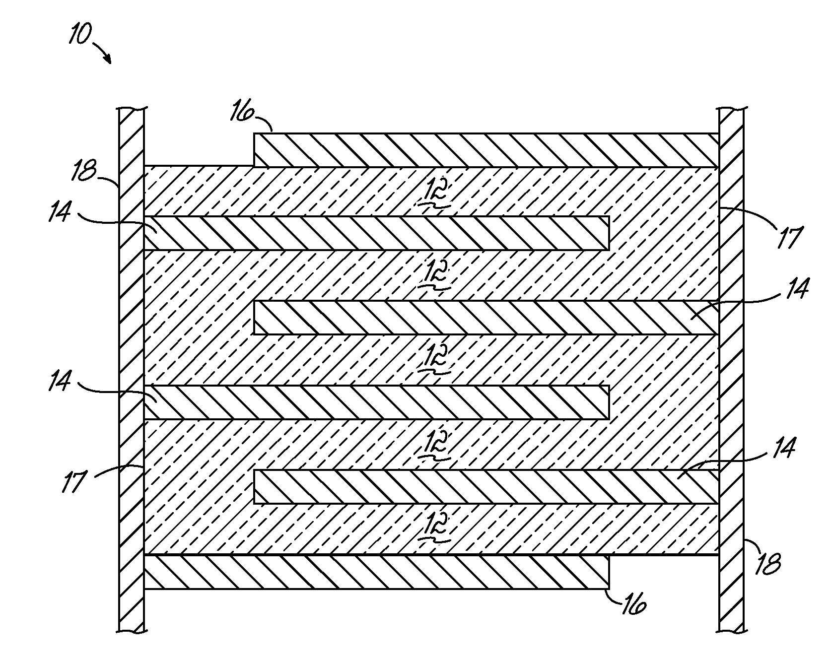
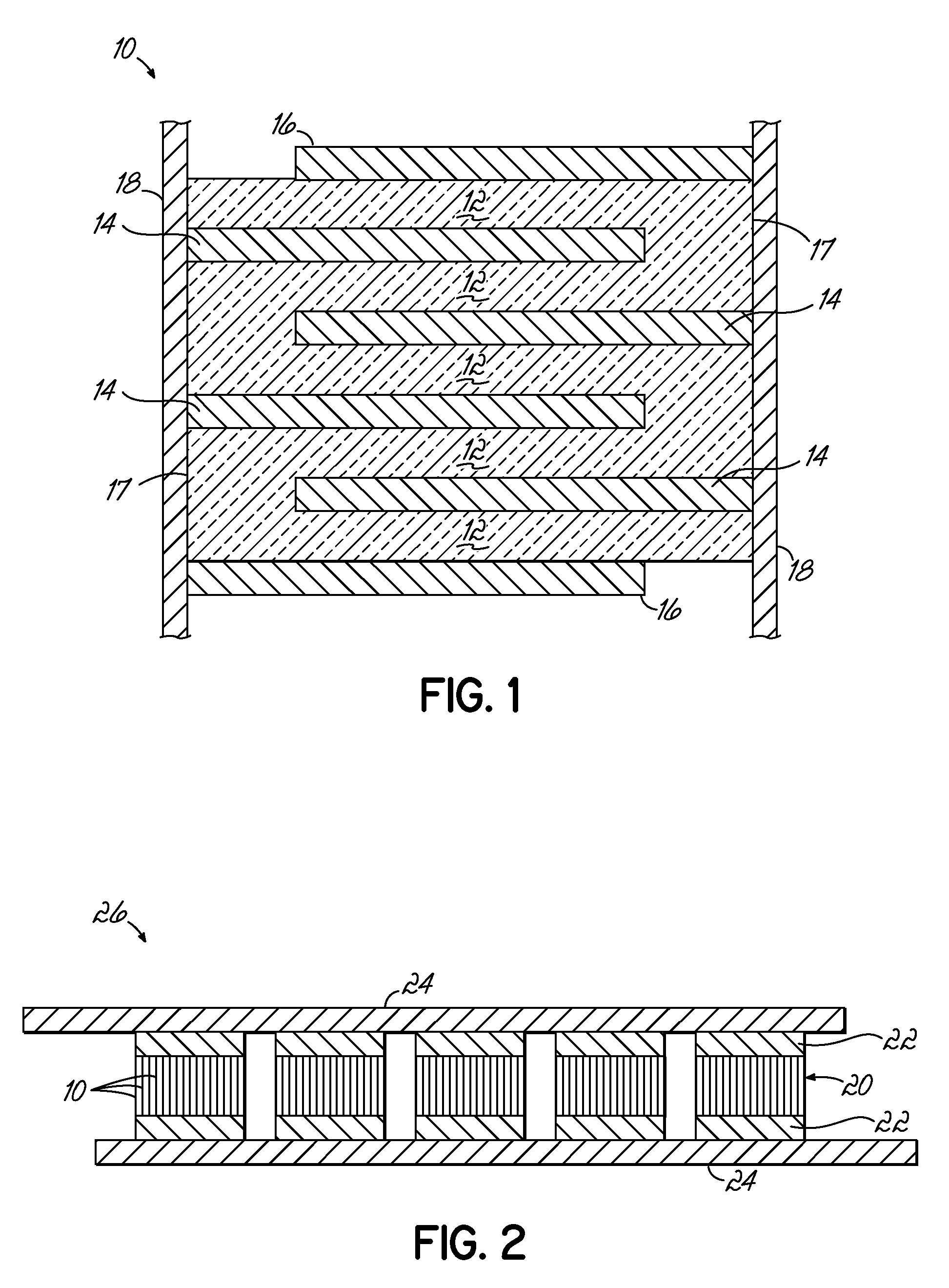
[0045]An exemplary embodiment of a multilayer ceramic capacitor 10, as disclosed herein, may be made from a batch powder containing a titanate powder of about 50 mol. % calcium titanate and about 50 mol. % strontium titanate. The titanate particles may be coated with about 0.25 wt. % niobium oxide (donor additive), about 0.05 wt. % manganese oxide (acceptor additive), and about 5.0 wt. % barium zinc borate (sintering aid). (All weight percents are based on the total weight of the titanate powder.) The batch powder is first milled in a plastic jar with zirconium oxide media for about 16 hours in solvent such as about 60 vol. % toluene, and about 40 vol. % ethyl alcohol containing a small amount of polyvinyl butyral binder (PVB) (e.g., about 5 wt. % PVB with respect to the weight of the solvent). A binder solution comprising about 16.1 wt. % PVB, about 24.8 wt. % dibutyl thalate plasticizer, and about 59.1 wt. % of the toluene / ethyl alcohol solvent is then added in a ratio of about 30...


PUM

PropertyMeasurementUnit
Temperatureaaaaaaaaaa
Lengthaaaaaaaaaa
Fractionaaaaaaaaaa

Abstract

A batch powder composition for preparing a non-ferroelectric, sintered dielectric ceramic; a multilayer ceramic capacitor thereof; and an energy storage device. The batch powder contains a titanate powder of at least one of CaTiO3, SrTiO3, or CaxSr1-xTiO3 where x=0 to 1, and an acceptor additive. A sintering aid and a donor additive also may be present in the batch powder. The batch powder may be sintered at temperatures of about 1050° C. or less. The ceramic contains a titanate from the titanate powder, the acceptor additive, and the optional sintering aids and donor additive. The multilayer ceramic capacitor is made of the sintered dielectric ceramic and may have electrodes of copper or a copper-nickel alloy. An energy storage device has electrical connections connected to the electrodes of the multilayer ceramic capacitor. The electrical connections may be in electrical communication with additional multilayer ceramic capacitors.

Description

FIELD OF THE INVENTION[0001]This invention relates to ceramic dielectric compositions, and in particular, to calcium and / or strontium titanate compositions for use in multilayer capacitors and energy storage devices.BACKGROUND OF THE INVENTION [0002]A demand exists for devices that store large amounts of electrical energy. For example, the advent of the electric vehicle, development of fuel cells, applications in space exploration and in the military, to name only a few, are driving the demand for these devices. One type of electrical energy storage device is the ceramic capacitor.[0003]Capacitors are reliable power sources for many applications, and the most common applications are in electronics. However, ceramic capacitors may replace more conventional energy storage devices in applications outside of the electronics market. For example, large banks of multilayer ceramic capacitors can replace lead-acid batteries. In addition to their bulk and excessive weight, batteries contain ...

Claims


Application Information

Patent Timeline
IPC IPC(8): H01G4/06C04B35/465C04B35/47
CPCC04B35/465H01G4/30C04B35/62805C04B35/6281C04B35/62813C04B35/62815C04B35/62818C04B35/62826C04B35/6455C04B2235/3201C04B2235/3203C04B2235/3206C04B2235/3208C04B2235/3213C04B2235/3215C04B2235/3217C04B2235/3224C04B2235/3225C04B2235/3227C04B2235/3229C04B2235/3236C04B2235/3239C04B2235/3241C04B2235/3251C04B2235/3256C04B2235/3258C04B2235/3262C04B2235/3272C04B2235/3275C04B2235/3281C04B2235/3284C04B2235/3286C04B2235/3409C04B2235/3418C04B2235/36C04B2235/445C04B2235/6025C04B2235/658C04B2235/6582C04B2235/6584C04B2235/661C04B2235/663C04B2235/77C04B2235/785H01G4/1227C04B35/47
Inventor BURN, IAN
Owner IAN BURN CONSULTING
Learn More