
Superconducting radiometry apparatus

a radiometry apparatus and superconducting technology, applied in the direction of superconductor devices, instruments, heat measurement, etc., can solve the problems of long processing time until the correction function is obtained, the output signal of the room temperature amplifier is the peak value, and it is impossible to accurately perform the correction by a correction method in an off-line manner, so as to achieve high resolving power measurement

Inactive Publication Date: 2010-01-28
HITACHI HIGH TECH SCI CORP
View PDF8 Cites 10 Cited by
  • Summary
  • Abstract
  • Description
  • Claims
  • Application Information

AI Technical Summary

Benefits of technology

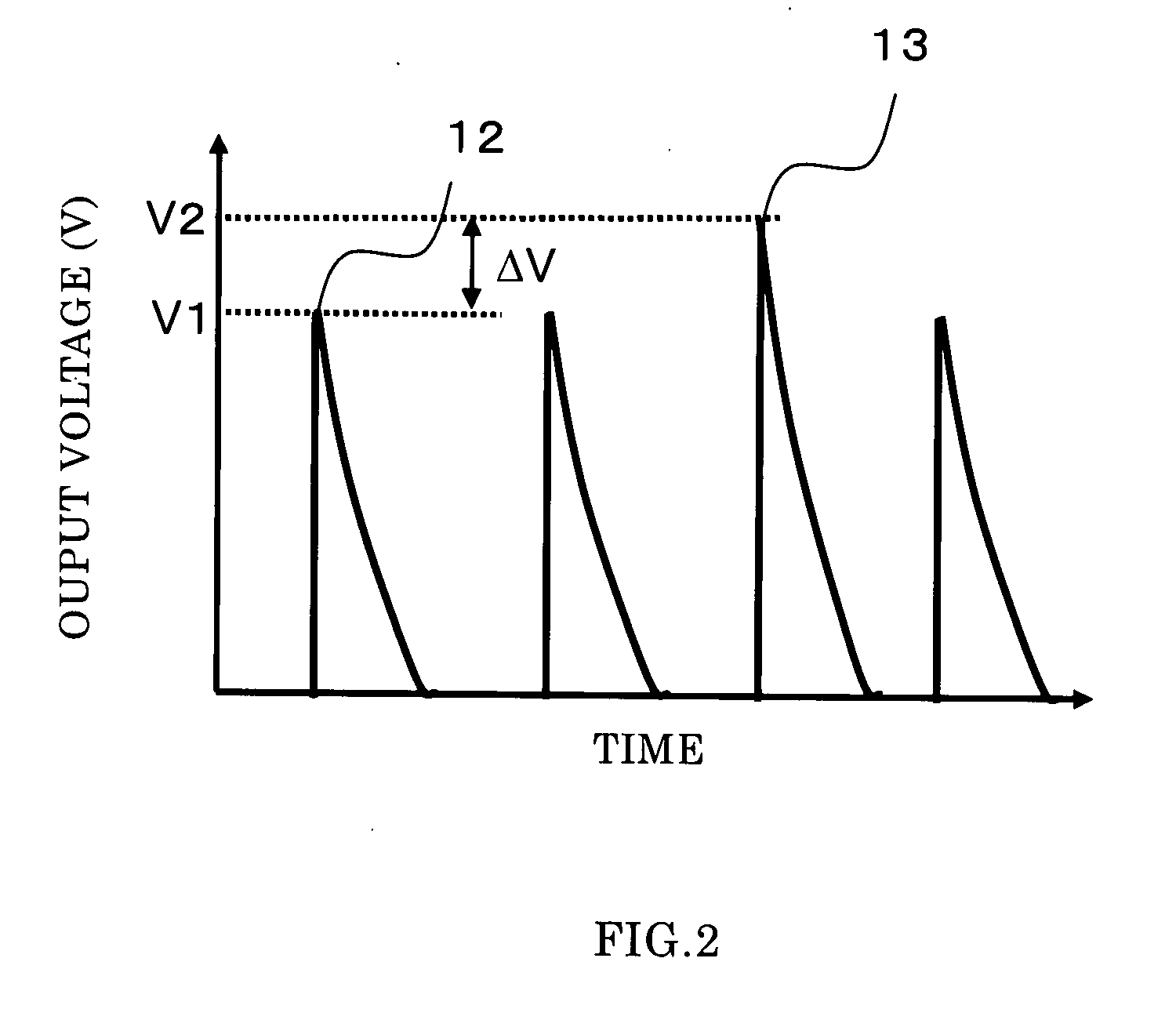
[0037]According to the superconducting radiometry apparatus concerned with the present invention, since it becomes possible to perform, while sample-measuring, the energy calibration in regard to the fluctuation of the peak value of the output signal, which is due to the radiation heat and the magnetic field from the outside, a high resolving power measurement becomes possible.

Problems solved by technology

However, in the superconducting radiometry apparatus like this, in a case where the energy of the entering X-ray is constant, although the peak value of the output signal from the room temperature amplifier becomes constant, there is such an issue that the peak value of the output signal from the room temperature amplifier changes by the fact that there occurs a thermal radiation following upon a temperature change of a thermal shield plate for thermally protecting the micro-calorie meter from an outside, or a resistance change of the micro-calorie meter, which follows upon a change in an external magnetic field exerted on the micro-calorie meter, so that a shift of the detected X-ray energy occurs.
However, in the superconducting radiation detection apparatus like the above, the following problems are left.
In the above energy calibration method, since the correction function is found and the correction of the peak value of the output signal is performed after the peak values of all output voltages are obtained by pulse-irradiating the X-ray, there is an issue that a processing time till the correction function is obtained becomes long.
Further, there is also the fact that the radiation heat and the magnetic field from the outside, which become a cause of a fluctuation of the peak value of the output signal from the room temperature amplifier, fluctuate every moment, so that it is impossible to accurately perform the correction by a correction method in an off-line.
Or, also in the superconducting radiation detection apparatus in which there is provided the feedback circuit in order to return the resistance of the micro-calorie meter to the origin, there remains such an issue that, similarly to the above, when there occurs the thermal radiation following upon the temperature change of the thermal shield plate for thermally protecting the micro-calorie meter from the outside, or the resistance change of the micro-calorie meter, which follows upon the change in the external magnetic field exerted on the micro-calorie meter, there occurs a shift of the detected X-ray energy with the peak value of the output signal from the room temperature amplifier being changed intact only by rapidly returning the resistance of the micro-calorie meter to the origin under a state including the resistance change by performing the feedback to the resistor by the feedback circuit.

Method used


Image

  • Superconducting radiometry apparatus
  • Superconducting radiometry apparatus
  • Superconducting radiometry apparatus

Examples


embodiment 1

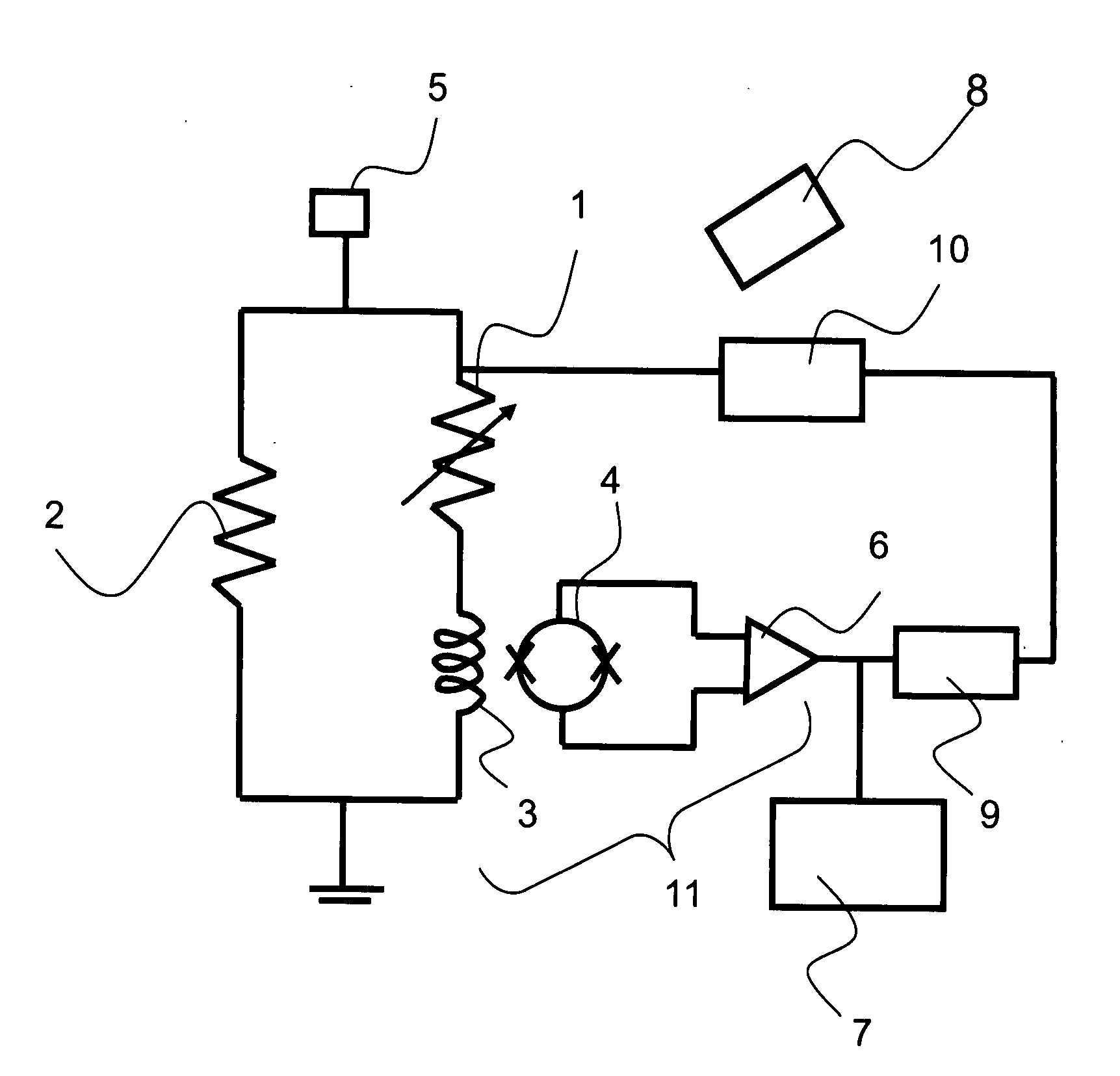
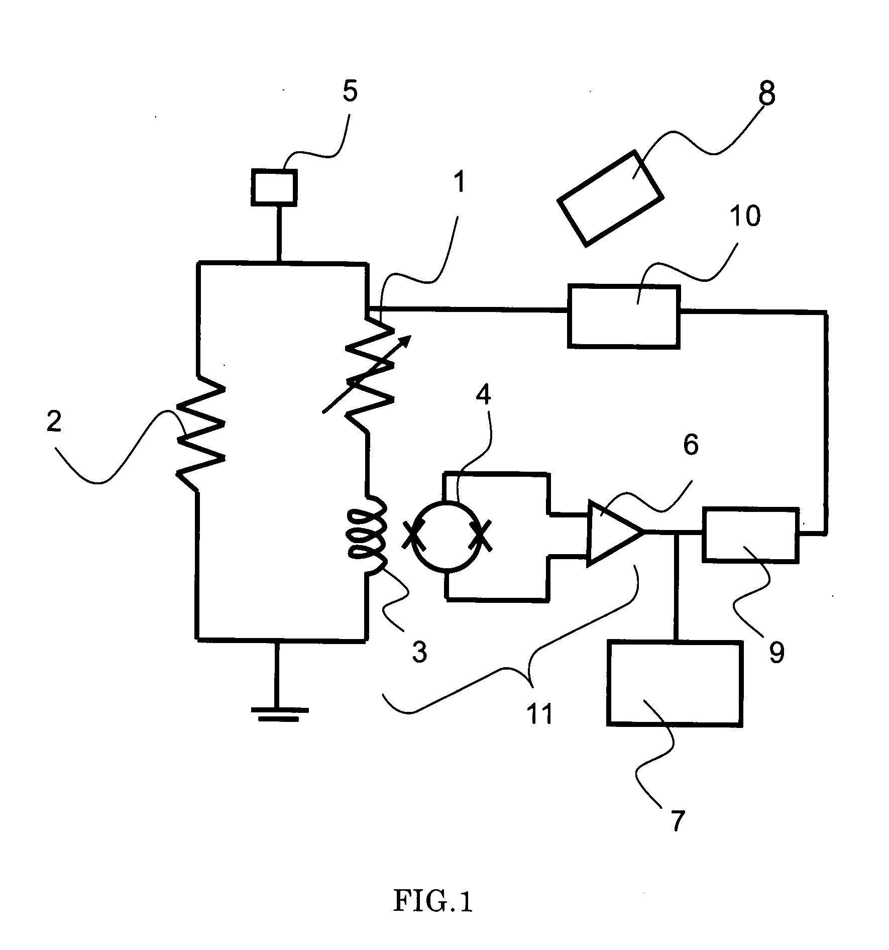
[0050]FIG. 1 shows the schematic constitution diagram of the superconducting radiometry apparatus concerned with the present embodiment.

[0051]The micro-calorie meter 1 in the present embodiment is constituted by the absorber for absorbing the X-ray, which uses a metal body, a metalloid, a superconductor or the like, the thermometer comprising the super conductor whose resistance value changes by the heat generated by the absorber, and the membrane for controlling the heat flow rate with which the heat generated in the absorber and the thermometer escape to the heat tub. In the present embodiment, for the absorber constituting the micro-calorie meter 1 there is used aluminum (Al), for the thermometer a material comprising two layers of titanium and gold, and for the membrane and the heat tub silicon (Si).

[0052]The input coil 3 is connected in series to the micro-calorie meter 1, and the shunt resistance 2 whose resistance value is smaller than the micro-calorie meter 1 is connected i...


PUM


Abstract

There is provided a superconducting radiometry apparatus capable of performing, while sample-measuring, an energy correction in regard to a fluctuation of a peak value of an output signal, which is due to a radiation heat and a magnetic field from an outside. The superconducting radiometry apparatus is constituted by comprising a micro-calorie meter detecting an energy of a radiant ray as a temperature change, a signal detection mechanism for detecting a displacement of an electric current flowing to the micro-calorie meter, a shunt resistance which is connected in parallel to the micro-calorie meter and whose resistance value is smaller than the micro-calorie meter, a bias electric source connected to the micro-calorie meter and the shunt resistance and applying a constant voltage, a heat addition device adding a constant and already-known heat quantity to the micro-calorie meter, a peak value monitor measuring a peak value corresponding to an added heat quantity within an output signal from the signal detection mechanism while synchronizing with a heat quantity addition from the heat addition device, and an energy correction device correcting, on the basis of an output from the peak value monitor, so as to become a peak value corresponding to the heat quantity from the heat addition device.

Description

BACKGROUND OF THE INVENTION[0001]1. Field of the Invention[0002]The present invention relates to a superconducting radiometry apparatus for performing an element analysis or an impurity inspection.[0003]2. Description of the Related Art[0004]In a radiometry apparatus used in the element analysis, the impurity inspection or the like, there is noted a superconducting radiation detection apparatus utilizing a superconductor detector capable of improving an energy resolving power of a conventional radiometry apparatus, which uses a semiconductor detector, by at least one figure.[0005]Since the energy resolving power of the radiometry apparatus using the semiconductor detector depends on an energy gap width that a semiconductor has, it is impossible to become below 130 eV. On the other hand, among the superconducting radiation detection apparatuses using the superconductor detector, there is especially expected a micro-calorie meter capable of making the energy resolving power into 10 eV...

Claims


Application Information

Patent Timeline
Patent Type & Authority Applications(United States)
IPC IPC(8): H01L39/00
CPCG01T1/26G01T1/1606
Inventor TANAKA, KEIICHIODAWARA, AKIKAZUNAKAYAMA, SATOSHI
Owner HITACHI HIGH TECH SCI CORP
Learn More