Multiple generator wind turbine

a wind turbine and generator technology, applied in the direction of machines/engines, electric generator control, final product manufacturing, etc., can solve the problems of high-power generators being more difficult to drive, high-power generators being more difficult to support long objects, and being quite heavy, etc., to achieve simple structure, reduce cost, and reduce the effect of weight and length

Inactive Publication Date: 2010-02-04
WILIC SARL
View PDF94 Cites 59 Cited by
  • Summary
  • Abstract
  • Description
  • Claims
  • Application Information

AI Technical Summary

Benefits of technology

[0009]The various embodiments of the present invention avoid the shortcomings of conventional wind power generators by providing a multiple generator wind turbine with a simpler structure, yielding higher power output for a given turbine diameter while keeping component diameter, weight, length, and cost down. Additionally, embodiments employ a largely hollow construction in which a maximum of ventilation possibilities is available for cooling and / or de-icing. In addition, embodiments afford a large degree of accessibility to the various components of the generator while providing a high level of structural stiffness. Embodiments further allow for the use of standard components, particularly in embodiments in which modular arrangements are employed, which can result in easier manufacture, assembly, and production. By virtue of the mounting of generators on opposite sides of the support structure according to embodiments, optimization of loads on the wind turbine can be realized.
[0017]The largely hollow structure of embodiments provides several advantages over the structures of the prior art. For example, housing electrical and electronic subsystems inside the nacelle affords excellent protection from lightning since the structure employs the principle of the Faraday cage. In addition, because the tubular structure is configured to accommodate the passage of adult humans, it permits easy access to the front portion of the nacelle and to the hub, which facilitates maintenance and repair work on other subsystems of the wind power generator. This also allows one to mount the hub from the inside.
[0018]The substantially hollow structure also facilitates use of the heat given off by equipment, such as power electronics, housed in the tower, as well as heat released by the generator itself. The heat can promote the chimney effect to guide warm air into the hub and from there into and through the rotor blades. The warm air can thus be used as a particularly efficient de-icing system in cooler times of the year, and provides a cooling effect for equipment in the generator as cooler air is drawn into and passes through the hollow structure. No external energy needs to be supplied during operation to heat the rotor blades. Thus, the heat given off by the generator and by the power electronics themselves is put to use in a simple fashion.
[0019]Additional cooling benefits are derived from the hollow structure since the components that produce heat are moved to the periphery of the generator. More specifically, the generator of embodiments places the windings on the inner periphery of the generator housing. Heat produced by the windings during electricity generation is easily conducted to the outer surface of the generator. By adding cooling fins on the outer surface according to embodiments, the heat can be transferred from the generator to the air stream passing over the generator during electricity production. The cooling fins preferably project transversely from the outer surface and are substantially equally spaced apart. While the fins extend longitudinally along the outer surface, they can also have a sweep or profile that takes into account disturbances in the air stream introduced by motion of the blades and / or the fins themselves to enhance effectiveness.
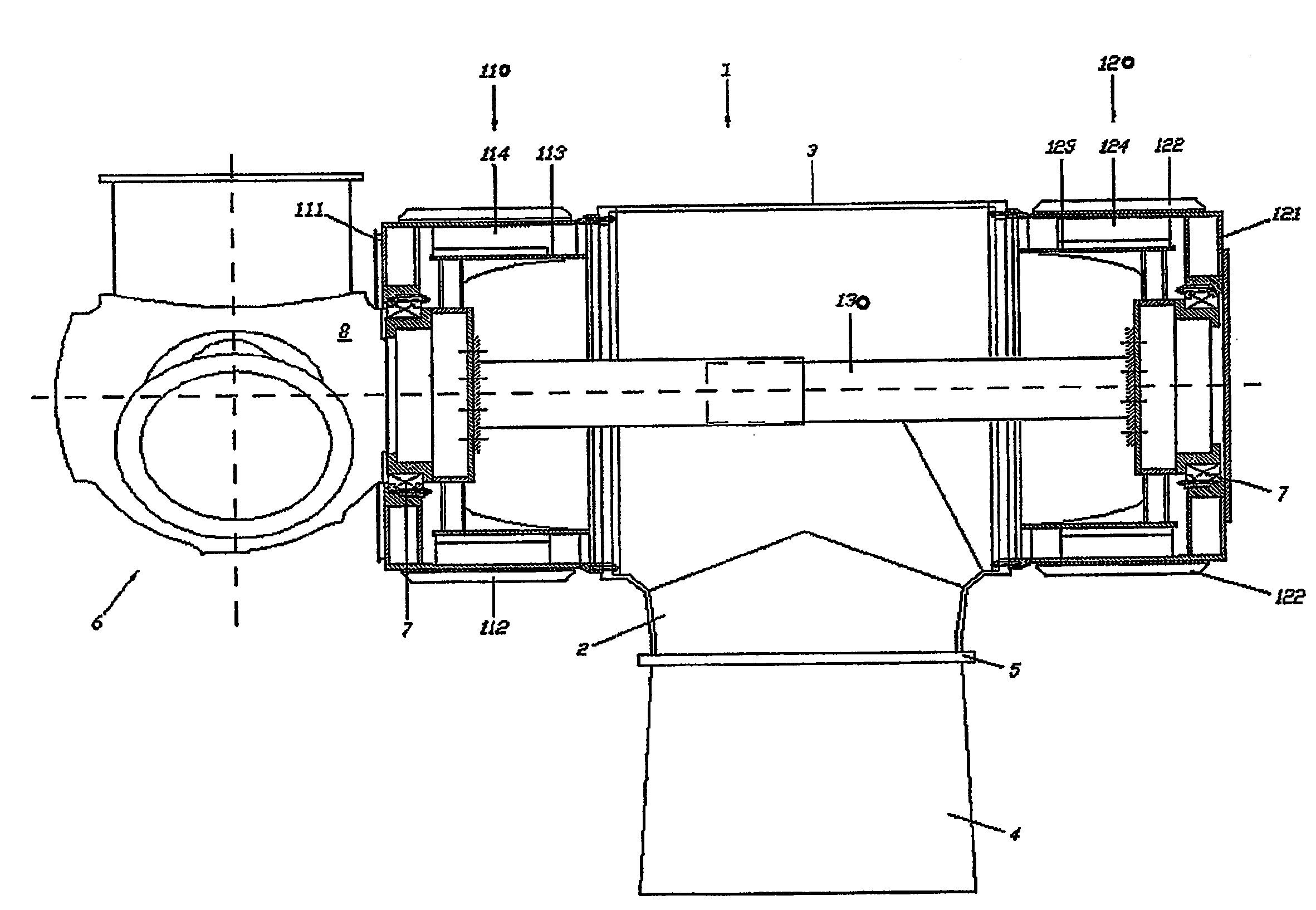
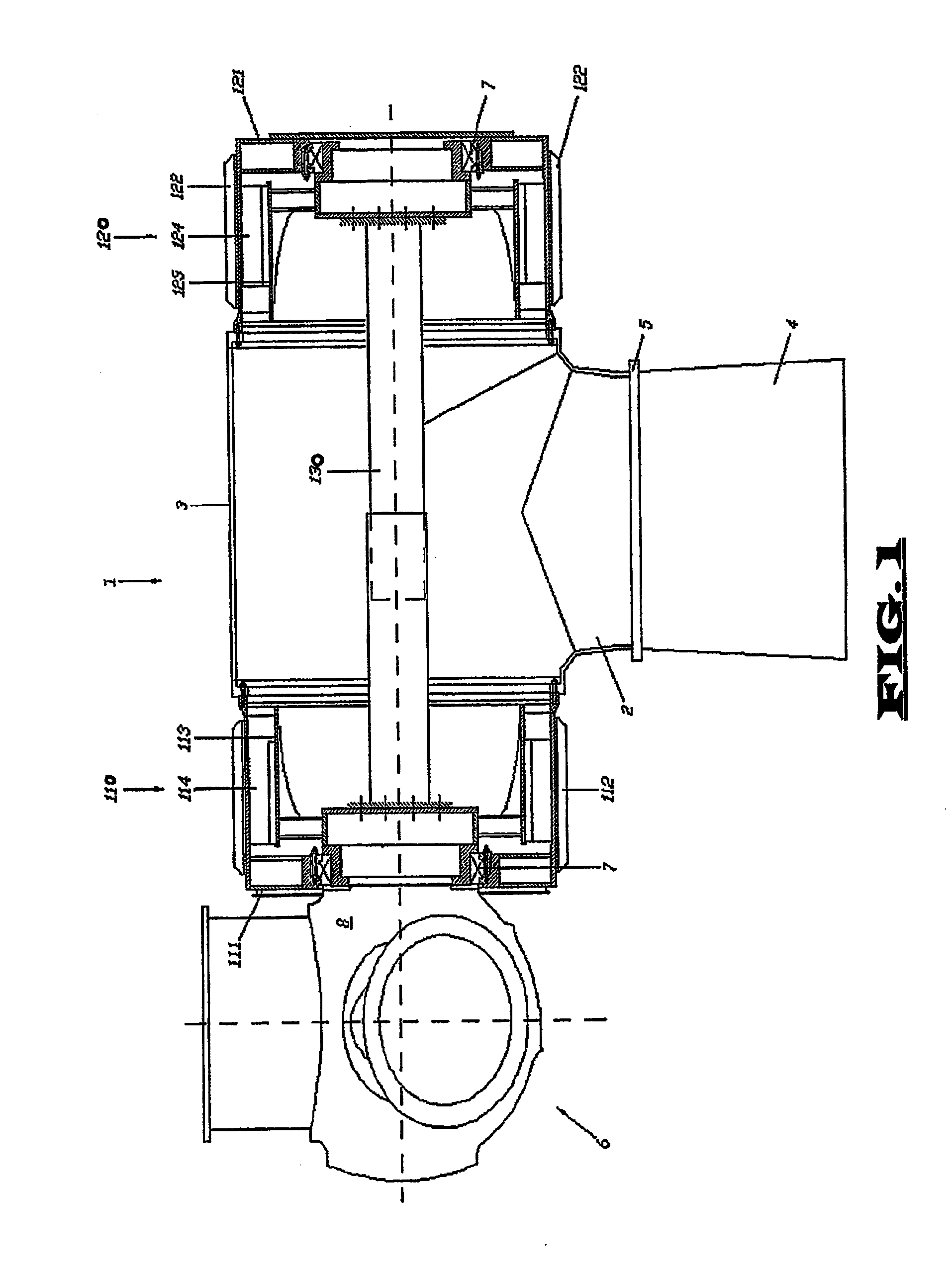
[0020]In embodiments, each generator has permanent magnets on an outer body and has windings / coils on an interior body. This yields a machine having a stator unit on the inside and a rotor on the outside. The magnets are preferably attached to the inner surface of the rotor in this arrangement, and the windings to the outer surface of the rotor shaft. The advantages of such a solution are a greater specific output, the possibility of using the total heat released by the generator for the de-icing system, and a simplification of the positioning of the power cables required to conduct the electric current from the generator to the tower.
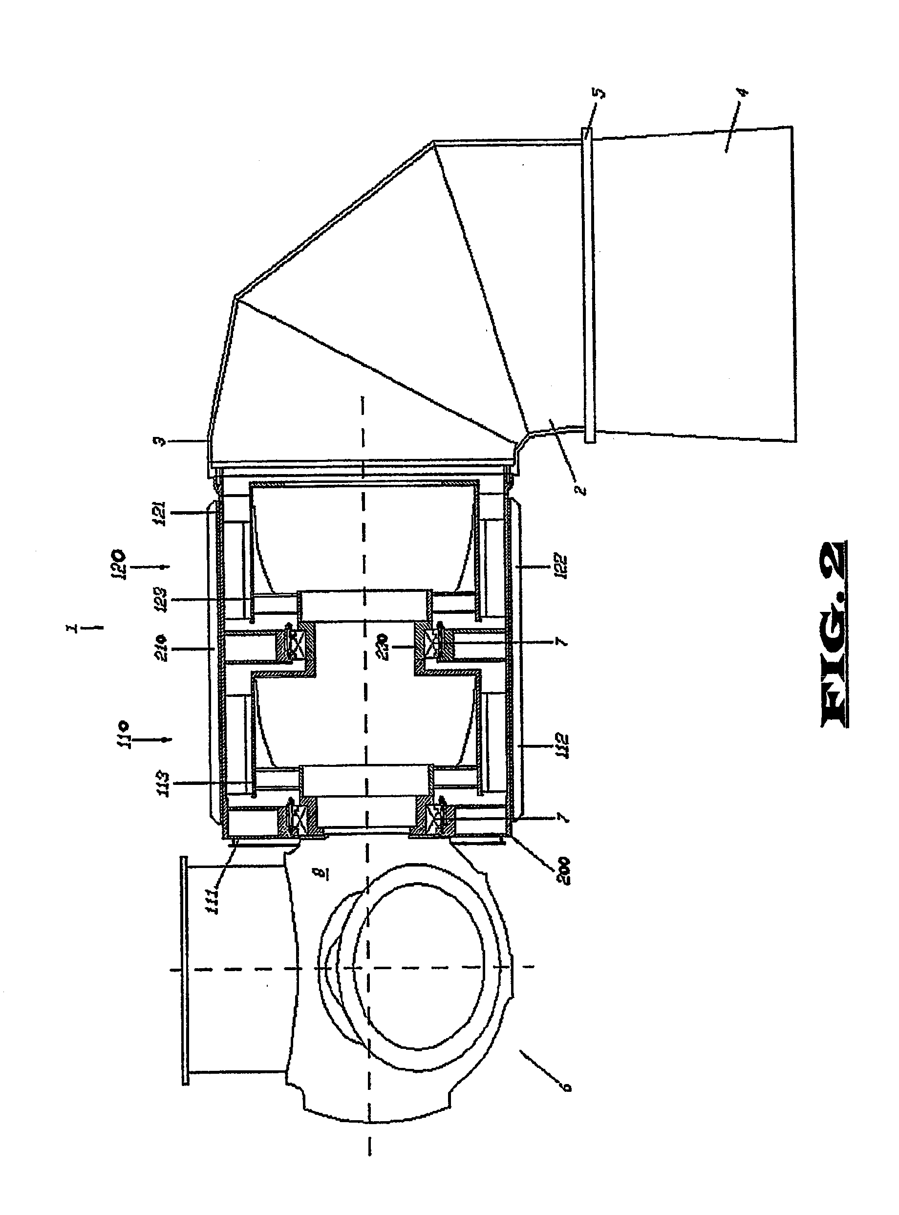
[0021]Preferably, each rotor is supported via a single bearing, preferably of the tapered roller type. The single bearing arrangement provides simplification of the generator mounting structure since only one-side need accommodate a bearing. The single bearing arrangement also eliminates hazardous eddy currents in the generator that form temporary circuits between the stator wall, the rotor wall, and roller bodies of the bearings disposed at the ends of the active portion (windings / coils) of the two bearing arrangement. Further, the single bearing arrangement simplifies adjustment processes of the bearing since the tapered rollers must be pre-stressed; embodiments with two bearings, one at each end of the generator, present design problems with respect to the construction tolerances and thermal deformation. The single bearing arrangement requires only one system of seals and lubrication concentrated in the front region of the generator. And the bearing typology used in the single bearing arrangement offers a high degree of rolling precision since pre-stressing the rollers substantially eliminates play in the bearing, as well as providing a low rolling resistance that increases generator productivity and efficiency.

Problems solved by technology

A difficulty associated with meeting these demands with single generator arrangements is that a high-power generator can be quite heavy, impeding assembly of the wind machine.
Increases in diameter and length present transportation and support-structure related problems in that the roads on which components will be transported can only handle so large an object and the structures involved in supporting a long object can be more complicated and expensive.
Additionally, such high-power generators tend to be more difficult to drive than lower-power generators, requiring higher initial operating wind speed and / or larger blades.
This arrangement does increase power output for a given diameter wind power generator, it does not overcome the weight issue described above in that the double-sided rotor and double-sided stator are both still single components.
In fact, this arrangement might even worsen the weight issue since there is more material on each of the rotor and stator.
While this is an interesting solution to the problem of obtaining more power from a given diameter generator, it introduces undesirable complexities in the support and wind harnessing structures of the device.
However, while possibly increasing power output for a given turbine diameter, weight is still an issue.
While this allows the use of two smaller generators to create a high power wind turbine, the use of completely independent drive and power collection systems introduces undesirable cost and complexity into the device.

Method used


Image

  • Multiple generator wind turbine
  • Multiple generator wind turbine
  • Multiple generator wind turbine

Examples


Embodiment Construction

[0041]In FIG. 1 a multiple power generator wind turbine is generally indicated by the reference number 1. A support structure 2 of the wind turbine 1 includes a connecting structure 3 that rests atop a support tower 4, preferably with a rotatable connection 5 allowing the single drive blade arrangement 6 to face the direction from which wind blows. The blade arrangement 6 includes a plurality of blades and drives two generators 110, 120. As shown in FIG. 1, the generators 110, 120 can be arranged with one generator 110 on a blade side of the support structure 2 and another generator 120 on the opposite side of the support structure. The housings 111, 121 of the generators 110, 120 each preferably carry a plurality of circumferentially-distributed cooling fins 112, 122 that draw heat away from the generators 110, 120, releasing the heat into the slipstream as air passes over the fins 112, 122. The blade side generator 110 includes a rotor 113 connected to the drive blade arrangement ...


PUM


Abstract

A multiple generator wind turbine employs a single blade arrangement to drive multiple generators. The multiple generators are preferably substantially tubular and can all be mounted on one side of the turbine support structure or can be divided, preferably symmetrically, on opposite sides of the support structure. Preferably, a single drive blade arrangement drives a rotor of a first generator and a shaft connects the first generator to a rotor of a second generator. Additionally, a clutch can be placed in the drive train between two generators to allow turbine operation at lower speeds. The substantially tubular nature of the turbine allows easy access by humans to the interior of the wind turbine and provides ready air flow through the wind turbine to the hub and blades for cooling of equipment therein and / or deicing of the blades.

Description

PRIORITY CLAIM[0001]This application is a national stage application of PCT / IT2006 / 000870, filed Dec. 22, 2006, the entire contents of which is incorporated herein.TECHNICAL FIELD[0002]The present invention relates to a wind power generator or turbine. More particularly, embodiments relate to a large-scale wind powered machine including two or more power generators and that accommodates humans within the workings for easy access and maintenance while providing efficient cooling of components and / or de-icing of blades. Embodiments are particularly suited to electrical power generation via wind power.[0003]Wind powered machines, particularly large scale electrical generators, include blades mounted on a hub attached to a rotor that rotates when wind passes over the blades. The rotation of the rotor is then used to drive machinery, such as pumps or electrical generators. In the case of electrical generators, the rotor will typically carry conductor windings / coils or magnetic field gene...

Claims


Application Information

Patent Timeline
Patent Type & Authority Applications(United States)
IPC IPC(8): F03D9/00
CPCF03D1/025F03D9/002F03D11/0025F05B2220/7066Y02E10/722F05B2230/601F05B2240/40Y02E10/725H02K7/1838F05B2220/7068F03D9/25F03D80/40Y02E10/72Y02E10/728Y02P70/50F03D13/20F03D15/00F03D80/60
Inventor PABST, OTTO
Owner WILIC SARL
Why Eureka
Try Eureka