Substrate for EUV mask blanks

a technology of euv mask and substrate, which is applied in the direction of photomechanical equipment, instruments, manufacturing tools, etc., can solve the problems of not being able to determine the measured stress as the stress of the substrate itself, and the conventional photolithography method is close to the resolution limit, etc., and achieves excellent flatness.

Active Publication Date: 2010-02-04
ASAHI GLASS CO LTD
View PDF3 Cites 62 Cited by
  • Summary
  • Abstract
  • Description
  • Claims
  • Application Information

AI Technical Summary

Benefits of technology

[0022]It is an object of the present invention to provide a substrate excellent in flatness that is to be used for a mask or for a mask blank for EUV lithography.
[0057]The substrate of the present invention has a good flatness, and as a result, it is possible to form a mask suitable for EUV exposure.
[0058]According to a preferred embodiment of the substrate of the present invention, it is possible to inhibit the influence of the EUV reflection light from a surface of the absorber layer along the periphery of a mask pattern area.

Problems solved by technology

However, the conventional photolithography method has been close to the resolution limit, while microsizing of semiconductor devices has been accelerated.
Further, in the process of Patent Document 4, although the detail is unclear, it seems that the stress of a glass called as a boule which is to be cut into a substrate, is measured, but it is not possible to determine the measured stress as the stress of the substrate itself.

Method used


Image

  • Substrate for EUV mask blanks
  • Substrate for EUV mask blanks
  • Substrate for EUV mask blanks

Examples


example 1

[0203]TiCl4 and SiCl4 as glass-forming materials of TiO2—SiO2, which have been each vitrified, are mixed. A mixed product obtained is heat-hydrolyzed (flame-hydrolyzed) in an oxygen-hydrogen flame to obtain TiO2—SiO2 glass fine particles, and they are deposited and grown on a seed rod rotating at a rotation speed of 25 rpm to form a porous TiO2—SiO2 glass body (Step (a)). Here, the variation widths in the gas temperatures of SiCl4 and TiCl4 in supply pipings are controlled to be within ±0.5° C., and a stirring mechanism of the source gases is provided at a point just before supplying SiCl4 and TiCl4 to a burner.

[0204]In order to improve a handling property, the porous TiO2—SiO2 glass body obtained is maintained at a temperature of 1,200° C. for 6 hours in the atmospheric air in a state that the glass body is deposited on a substratum, and thereafter, the glass body is taken out from the seed rod.

[0205]Thereafter, the porous TiO2—SiO2 glass body taken out is placed in an electric fur...

example 2

Comparative Example

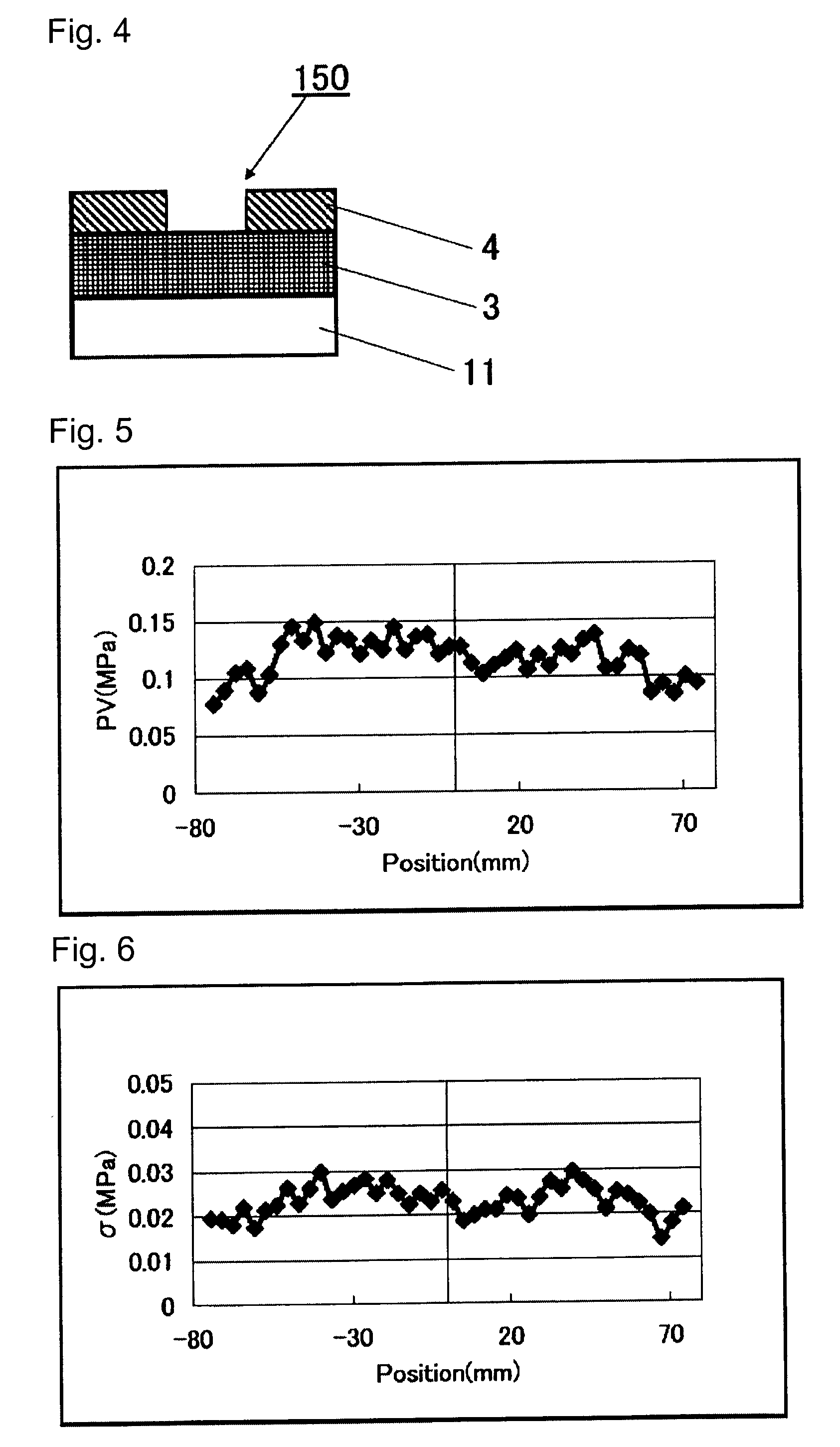
[0218]A substrate is prepared in the same manner as Example 1 except that the angle of the burner is set to 4° with respect to the vertical direction in Step (a). Also in this Example, the number of particles (foreign substances) having a size of at least 60 nm present on a surface of each substratum is measured by a photomask surface defect inspection machine, and only substrates in a level of no problem are selected.

[0219]With respect to each substrate obtained, the maximum variation (PV) of the stress, the standard deviation(σ) of the stress and the surface roughness (rms) are measured. Tables 1 to 6 show the results, and FIGS. 8, 9 and 10 show the graphs.

TABLE 1Example 1Example 2MPositionStressStressStressStressNo.(mm)PV (MPa)σ (MPa)PV (MPa)σ (MPa)1−74.1750.0780.0200.6060.1082−70.7250.0900.0190.4720.0833−67.2750.1050.0180.6670.1154−63.8250.1090.0220.5580.0835−60.3750.0880.0170.5580.1156−56.9250.1030.0210.4830.1027−53.4750.1300.0220.7570.1568−50.0250.1460.0261....

example 3

[0221]A substrate is prepared in the same manner as Example 1 except that the following Step (d-1) and Step (d-2) are carried out instead of Step (d).

[0222]A transparent TiO2—SiO2 glass body obtained is heated at 1,700° C. in a carbon mold having a cubic shape of 175 mm cube, to obtain a formed TiO2—SiO2 glass body (first formed product) having a cubic shape of 175 mm cube (Step (d-1)).

[0223]The outer periphery of the formed TiO2—SiO2 glass body obtained is cut so as to have a cross section of 123 mm square centering on he original center line, and it is heated again at 1,700° C. in a cubic carbon mold of 175 mm cube, to thereby obtain a cubic formed TiO2—SiO2 glass body (second formed body) of 175 mm cube (Step (d-2)).

[0224]Also in Example 3, the number of particles (foreign substances) having a size of at least 60 nm present on a surface of each substratum is measured by a photomask surface inspection machine, and only substrates in a level of no problem are selected.

[0225]With re...


PUM

PropertyMeasurementUnit
surface roughnessaaaaaaaaaa
fictive temperatureaaaaaaaaaa

Abstract

A substrate that is suitable for an EUV mask or an EUV mask blank and excellent in flatness, is provided.A substrate for an EUV mask blank, which is made of a silica glass containing from 1 to 12 mass % of TiO2, wherein the surface roughness (rms) in a surface quality area of the substrate is at most 2 nm, and the maximum variation (PV) of the stress in the surface quality area of the substrate is at most 0.2 MPa.

Description

BACKGROUND OF THE INVENTION[0001]1. Field of the Invention[0002]The present invention relates to a substrate suitably used for a mask or a mask blank for EUV lithography.[0003]2. Discussion of Background[0004]In the semiconductor industry, a photolithography method using visible light or ultraviolet light has been employed as a technique for writing, on a Si substrate or the like, a fine pattern, which is required for forming an integrated circuit comprising such a fine pattern. However, the conventional photolithography method has been close to the resolution limit, while microsizing of semiconductor devices has been accelerated. In the case of the photolithography method, it is said that the resolution limit of a pattern is about ½ of an exposure wavelength, and that even if an immersion method is employed, the resolution limit is about ¼ of an exposure wavelength. Even if an immersion method using an ArF laser (193 nm) is employed, it is estimated that the resolution limit is abo...

Claims


Application Information

Patent Timeline
Patent Type & Authority Applications(United States)
IPC IPC(8): G03F7/20G03F1/00C03C3/04G03F1/22G03F1/24G03F1/60H01L21/027
CPCB82Y10/00B82Y40/00C03B19/1415C03B19/1453C03B19/1469C03B19/1492G03F1/24C03B2201/42C03C3/06C03C2201/14C03C2201/21C03C2201/23C03C2201/42C03B2201/21Y02P40/57
Inventor KOIKE, AKIOEBIHARA, KEN
Owner ASAHI GLASS CO LTD
Why Eureka
Try Eureka