Modeling of pharmaceutical propagation

Inactive Publication Date: 2010-02-04
BAJER MEDIKAL KEHA INK
View PDF100 Cites 50 Cited by
  • Summary
  • Abstract
  • Description
  • Claims
  • Application Information

AI Technical Summary

Benefits of technology

[0062]Benefits provided by various embodiments of this invention include, but are not limited to: more consistent enhancement for subsequent image processing, reduced contrast or fluid loading for some patients, increased contrast dose to achieve sufficient image contrast

Problems solved by technology

The imaging of soft tissue, vasculature, and other structures is not easily accomplished with CT scanners because these structures do not differentially attenuate X-Rays to an appreciable degree.
With such new technologies, however, arise new challenges for application in daily practice.
Although using fixed protocols (whether uniphasic, biphasic or multiphasic) for delivery simplifies the procedure, providing the same amount of contrast media to different patients under the same protocol can produce very different results in image contrast and quality.
Not having explicit measurements of cardiac output is a substantial drawback to Bae's approach, despite attempts to approximate the value based upon the patient's age, weight, and height.
Furthermore, there is no consideration for implementation of the PK models in a controller framework.
Moreover, the PK model of Bae does not consider the effects of pulsatile flow, vessel compliance, and local blo

Method used


Image

  • Modeling of pharmaceutical propagation
  • Modeling of pharmaceutical propagation
  • Modeling of pharmaceutical propagation

Examples


Embodiment Construction

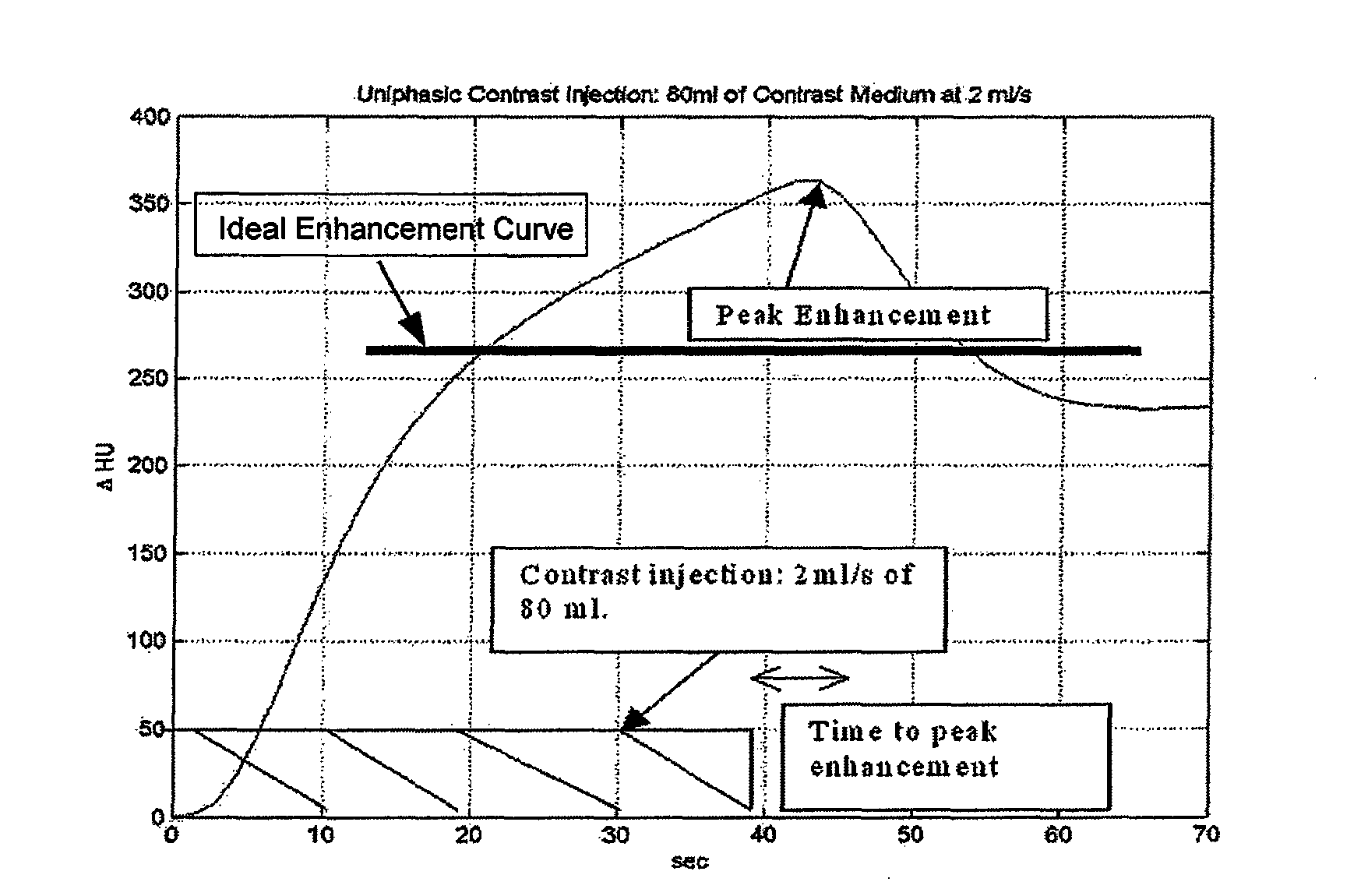
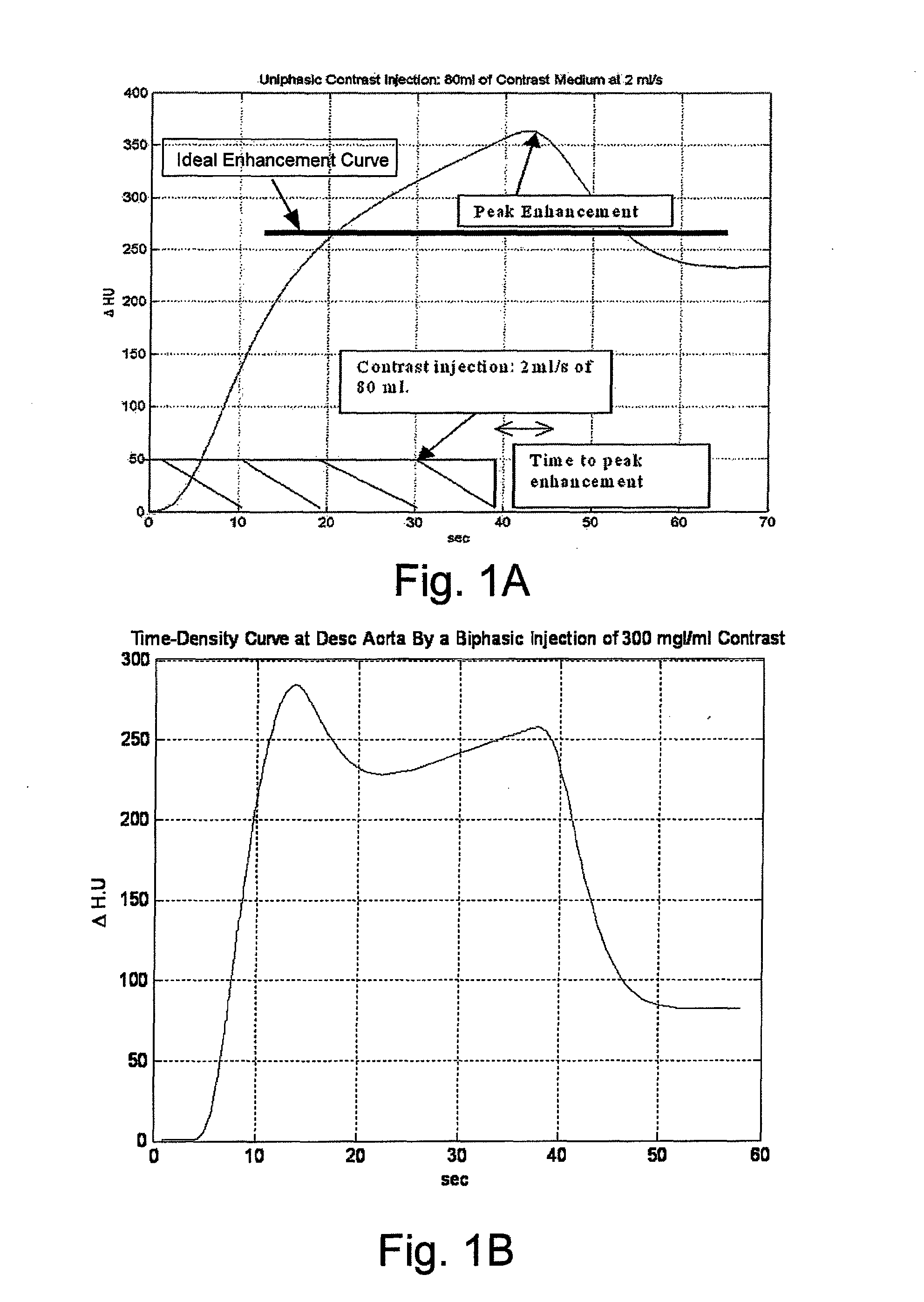
[0091]FIG. 1A illustrates a typical time-enhancement curve obtained with a single phase contrast-enhanced CT scan of a blood vessel. The units, HU are Houndsfield Units, a measure of X-ray absorption density that is translated into signal intensity in an image. FIG. 1A illustrates a peak enhancement at a time of about 45 seconds. In many imaging procedures, the time-enhancement curve is preferably uniform around a specified level (as illustrated by the thick black line in FIG. 1A). When the curve is not uniform or flat, a less than optimum image may result in an erroneous diagnosis in such imaging procedure. As advances in scanning technology enable image acquisition in less time, uniformity of enhancement over longer time periods may decrease somewhat in importance, but proper timing of a scan relative to contrast injection and avoidance of too much contrast or too little contrast remain important.

[0092]FIG. 1B illustrates a typical time-enhancement curve obtained with a dual phase...


PUM


Abstract

A method of delivering a contrast enhancing fluid to a patient using an injector system, including: determining at least one patient transfer function for the patient based upon data specific to the patient and, the at least one patient transfer function providing a time enhancement output for a given input; determining a desired time enhancement output; using the at least one patient transfer function to determine an injection procedure input; and controlling the injector system at least in part on the basis of the determined injection procedure input. The injection procedure input can determined considering at least one operational limitation or constraint of the injector system. A method of modeling propagation of a pharmaceutical fluid in a patient, includes: collecting data corresponding to a time response curve resulting from injection of the fluid; and determining at least one mathematical model describing the data. The mathematical model can, for example, be a model which is not determined by a continuous or a discrete-time Fourier deconvolution of the data. A method of controlling injection of a pharmaceutical fluid into a patient using an injector in a medical procedure, includes: collecting data corresponding to a patient response curve resulting from injection of the fluid; determining at least one mathematical model describing the data; and controlling the injector during the medical procedure to control injection of the fluid into the patient to create patient response at least in part on the basis of the mathematical model. A method of controlling injection of a contrast medium into a patient using an injector in a medical imaging procedure using an imaging scanner, includes: determining at least one mathematical model to predict a time enhancement response resulting from injection of the contrast medium; determining an injection protocol to approximate a predetermined time enhancement response in the patient by determining a constrained input solution to the mathematical model; and using the injection protocol to control the injector during the medical imaging procedure to control injection of the contrast medium into the patient to create an image of a region of interest. Patient transfer functions for the patient of the present invention can also be based at least in part on a measurement of cardiac output of the patient. Likewise, mathematical models of the present invention can be based at least in part on a measurement of cardiac output of the patient.

Description

CROSS-REFERENCE TO RELATED APPLICATIONS[0001]This application claims benefit of PCT Application US07 / 087,765, filed Dec. 17, 2007, and U.S. Provisional Patent Application Ser. No. 60 / 877,776 filed Dec. 29, 2006, the contents of which are hereby incorporated by reference.BACKGROUND OF THE INVENTION[0002]The present invention relates generally to modeling of the propagation of a pharmaceutical in a patient, and, particularly, to modeling of contrast media propagation in a patient for use in imaging procedures.[0003]The following information is provided to assist the reader to understand the invention disclosed below and the environment in which it will typically be used. The terms used herein are not intended to be limited to any particular narrow interpretation unless clearly stated otherwise in this document. References set forth herein may facilitate understanding of the present invention or the background of the present invention. The disclosure of all references cited herein are ...

Claims


Application Information

Patent Timeline
IPC IPC(8): A61B6/00G06F17/10
CPCA61B5/029A61B5/7257A61B6/03A61B6/481A61B6/503A61B6/583A61B8/0891A61B8/13G01R33/5601A61B6/507A61B6/504A61B5/0295
Inventor KALAFUT, JOHN
Owner BAJER MEDIKAL KEHA INK
Why Eureka
Try Eureka