Electron beam exciter for use in chemical analysis in processing systems

a technology of chemical analysis and exciter, which is applied in the direction of cathode ray tube/electron beam tube, nuclear engineering, therapy, etc., can solve the problems of process failure to produce a traditional oes endpoint, traditional monitoring method failure to detect the endpoint, and reactive species and effluents of the etching process are not excited, so as to achieve greater electrical potential and electron energy imparted

Active Publication Date: 2010-02-11
VERITY INSTR +1
View PDF105 Cites 338 Cited by
  • Summary
  • Abstract
  • Description
  • Claims
  • Application Information

AI Technical Summary

Benefits of technology

[0009]The present invention is directed to an electron beam exciter, electron beam excitation system and method for exciting gases using an electron beam exciter. The electron beam exciter generally comprises a variable density electron source for generating a cloud of electrons in an electron source chamber and a variable energy electron extractor for accelerating electrons from the electron source chamber as an electron beam and into a gas sample for fluorescing. The electron density (concentration) of the electron beam is variably controlled by adjusting the excitation power applied to the electron source. The electrons in the electron source chamber assume a reference potential by contacting a conductive surface at the chamber that is held at the reference potential, typically near ground electrical potential. The electron energy of the electron beam is variably controlled by adjusting a voltage to the electron extractor electrode, which changes the charge on the electrode. The potential difference between electron extractor electrode and the reference potential at

Problems solved by technology

Recent new plasma etch processes have been encountered in which this traditional monitoring method is failing to detect the endpoint.
However, neither the reactive species nor the effluents of the etch process are excited into high enough energy state(s) needed to produce fluorescence.
The absence of fluorescence in the reaction chamber is the reason these “dark plasma” processes fail to produce a traditional OES endpoint.
Although these processes do excite the gas species to fluorescence that can be detected in the process chamber, the resulting spectra do not display the one or more wavelength intensity changes required for successful OES endpoint detection.
However, they suffer from two problems

Method used


Image

  • Electron beam exciter for use in chemical analysis in processing systems
  • Electron beam exciter for use in chemical analysis in processing systems
  • Electron beam exciter for use in chemical analysis in processing systems

Examples


Embodiment Construction

[0061]

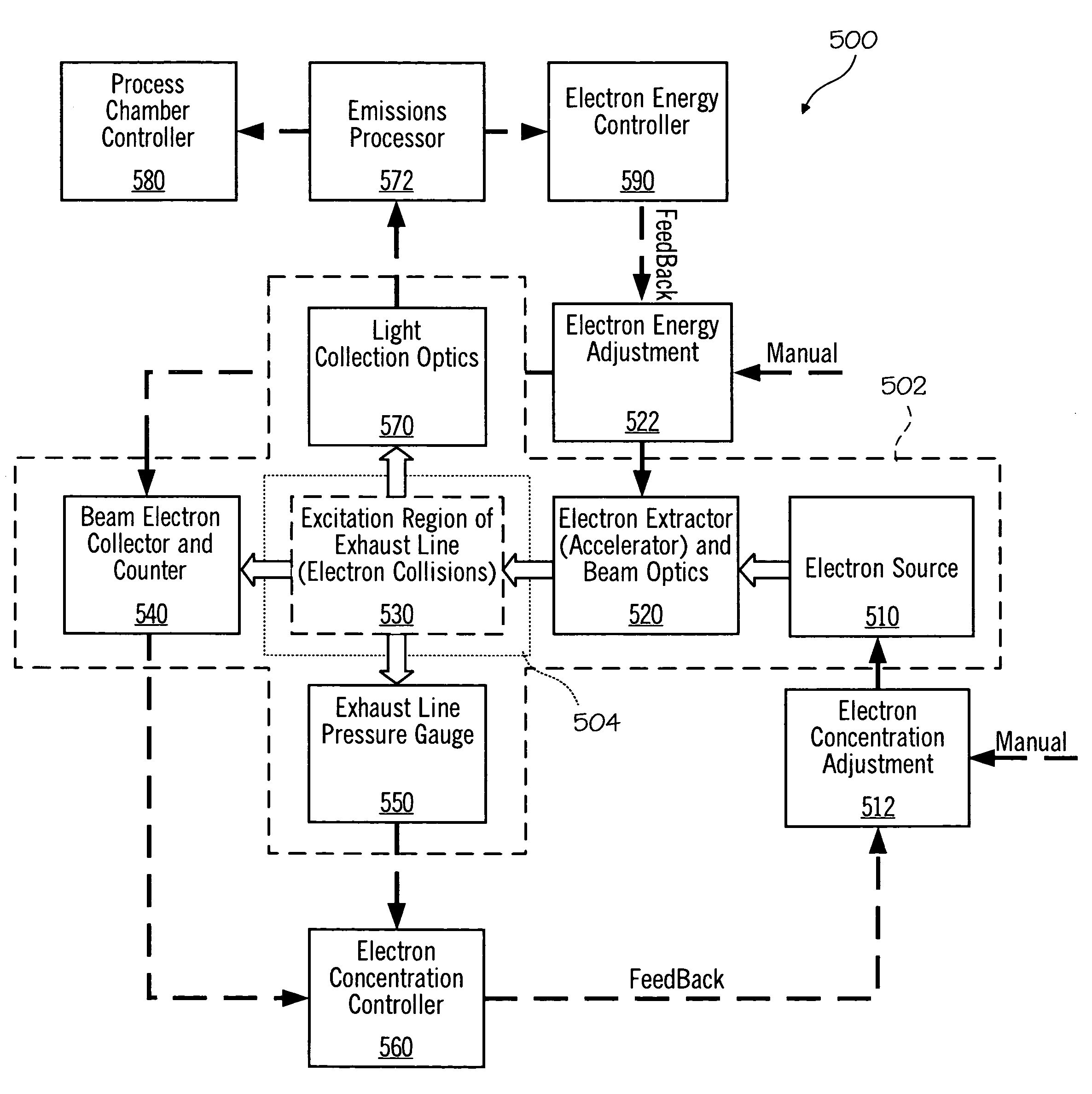
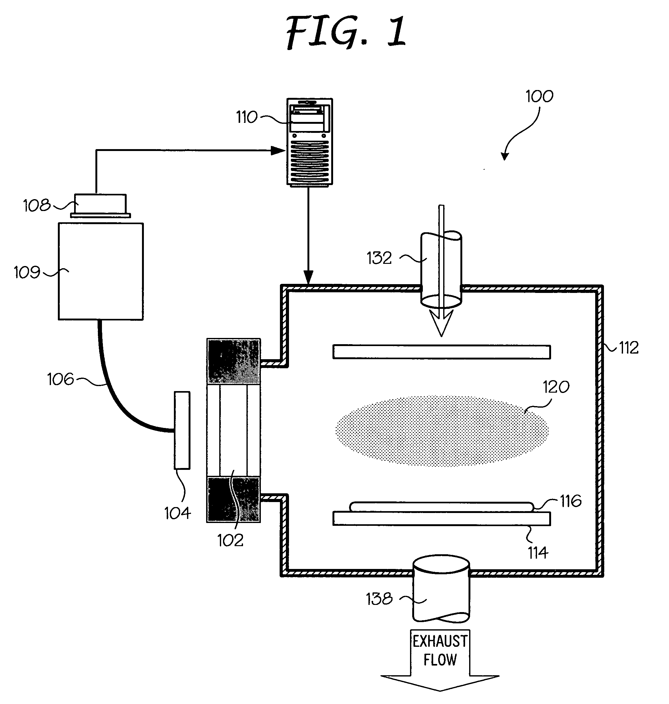
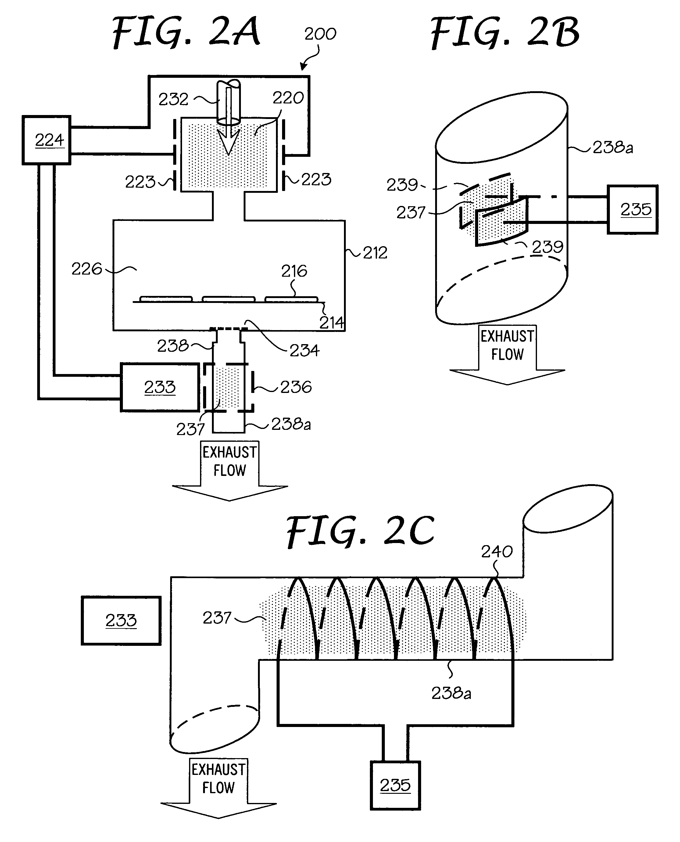
Element Reference Number Designations 100:OES measurement apparatus 102:Window 104:Collecting optics 106:Optical fiber 108:Sensor 109:Spectrograph 110:Process controller 112:Processing chamber 114:Wafer support 116:Wafer 120:Plasma 132:Process gas inlet 138:Processing chamber gas outlet 200:Exhaust plasma excitation apparatus 202:Window 204:Collecting Optics 206:Optical Fiber 208:Sensor 209:Spectrograph 210:Process Controller 212:Processing Chamber 214:Wafer Support 216:Wafer 220:First plasma region 223:Plasma electrodes 224:High frequency power source 226:Etching region 232:Process gas inlet 233:Emission spectrum detection mechanism 234:Shield plate with wire mesh pattern 235:Secondary high frequency power source 236:Second plasma region 237:Discharge plasma 238:Exhaust pipe 238a:Quartz exhaust pipe 239:Capacitive electrode plates 240:Induction coils 310:Treatment chamber 311:Opposed electrode 312:Sample 313:Discharge space 314:Insulating material 315:Exhaust port 316:Baffle ...


PUM


Abstract

The present invention is directed to a gas line electron beam exciter, gas line electron beam excitation system and method for exciting a gas using an electron beam exciter. The electron beam exciter generally comprises a variable density electron source for generating a cloud of electrons in an electron chamber and a variable energy electron extractor for accelerating electrons from the electron chamber as an electron beam and into an effluent stream for fluorescing species in the effluent. The electron density of the electron beam is variably controlled by adjusting the excitation power applied to the variable density electron source. The electrons in the electron chamber reside at a reference electrical potential of the chamber, typically near ground electrical potential. The electron energy of the electron beam is variably controlled by adjusting an electrical potential across the variable energy electron extractor, which energizes the electrons through an extraction hole of the chamber and toward the extractor. The greater the difference in the electrical potential between the electron extractor and the electron source, the higher the energy imparted to the electrons in the electron beam. The excitation power applied to the electron source can be adjusted independently from the electron energy of the electron beam, thereby altering the electron density of the electron beam without changing the energy level of the electrons of the electron beam.

Description

CROSS-REFERENCE TO RELATED APPLICATION[0001]This application is related to and claims the benefit of co-pending U.S. Provisional Application Ser. No. 61 / 135,163, filed on Jul. 17, 2008 and entitled “Electron Beam Exciter for Use in Chemical Analysis in Processing Systems,” and co-pending U.S. provisional application Ser. No. ______ (Attorney Docket No. 946959600042P2), filed on Jul. 15, 2009 and entitled “Electron Beam Exciter for Use in Chemical Analysis in Processing Systems,” which are each incorporated herein by reference.BACKGROUND OF THE INVENTION[0002]The present invention relates generally to an apparatus for producing fluorescence in the gases from a reactor chamber.[0003]Optical emission spectroscopy (OES) endpoint detection relies on the change in intensity of light emitted from the gas species involved with the etch process. During steady-state etching of the etch layer, the reactant gases and reaction gas products are excited by the plasma causing fluorescence of light ...

Claims


Application Information

Patent Timeline
IPC IPC(8): H01J31/00H01J29/00
CPCH01J37/06H01J37/32972H01J37/32935
Inventor HOSCH, JIMMY W.GOECKNER, MATTHEW J.WHELAN, MIKEKUENY, ANDREW WEEKSHARVEY, KENNETH C.THAMBAN, P.L. STEPHAN
Owner VERITY INSTR
Why Eureka
Try Eureka