Control system of secondary battery and hybrid vehicle equipped with the same

a control system and secondary battery technology, applied in the direction of propulsion parts, electric devices, propulsion using engine-driven generators, etc., can solve problems such as accuracy problems, and achieve the effect of preventing overcharge and overdischarge and rapid deterioration of secondary batteries

Active Publication Date: 2010-02-11
TOYOTA JIDOSHA KK
View PDF5 Cites 72 Cited by
  • Summary
  • Abstract
  • Description
  • Claims
  • Application Information

AI Technical Summary

Benefits of technology

[0036]According to the above hybrid vehicle equipped with the charge/discharge system of the secondary battery, the overall drive force required in the vehicle can be ensured while restricting the charge/discharge of the secondary battery of which load is formed of the electric motor, and giving consideration for preventing the overcharge and overdischarge as well as the rapid deterioration in the secondar...

Problems solved by technology

According to the above boundary conditions, however, a reacting quantity at the interface depends on a temperature difference, and does not match with an...

Method used


Image

  • Control system of secondary battery and hybrid vehicle equipped with the same
  • Control system of secondary battery and hybrid vehicle equipped with the same
  • Control system of secondary battery and hybrid vehicle equipped with the same

Examples


first embodiment

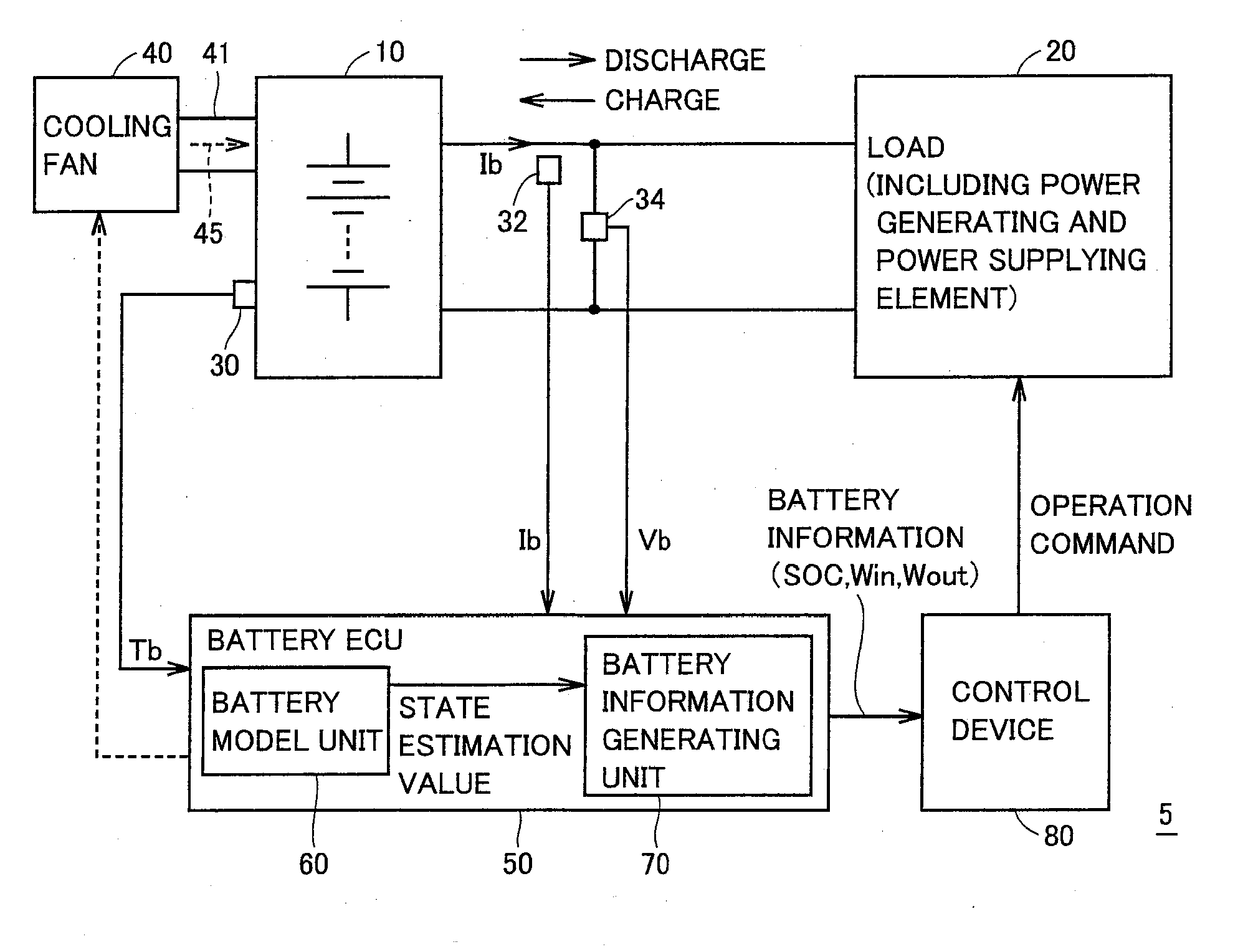
[0073]FIG. 1 is a schematic block diagram illustrating a structure of a power supply system controlled by a control system of a secondary battery according to an embodiment of the invention.

[0074]Referring to FIG. 1, a power supply system 5 includes a secondary battery 10, a load 20 and a cooling fan 40 of the secondary battery as well as a battery ECU (Electronic Control Unit) 50 and a control device 80 which are formed of ECUs. Each ECU is typically formed of a microcomputer for executing predetermined sequences and predetermined arithmetic operations that are programmed in advance as well as a memory such as a RAM (Random Access Memory), a ROM (Read Only Memory) or the like. Battery ECU 50 and control device 80 implements a “control system” that executes charge / discharge restrictions to be described below.

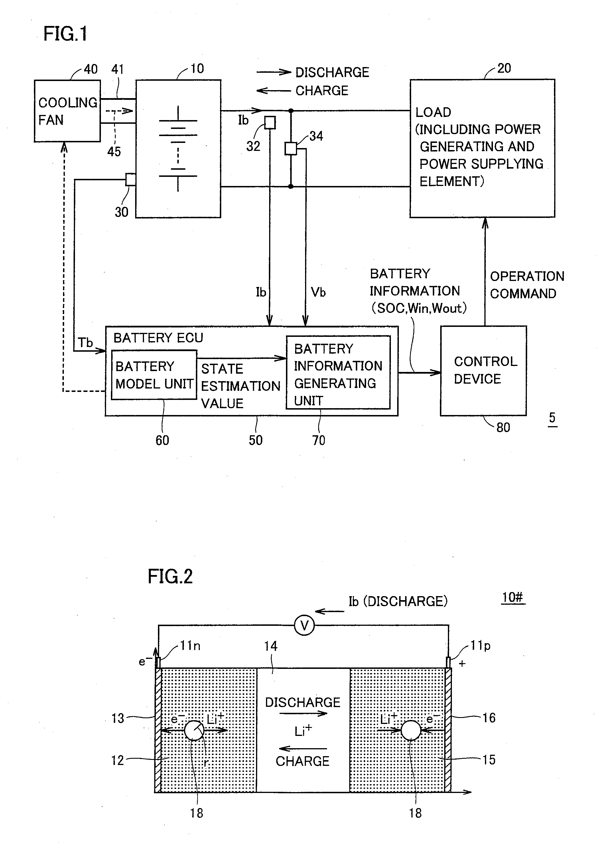
[0075]Chargeable and dischargeable secondary battery 10 is typically formed of a lithium ion battery. The lithium ion battery has output characteristics that vary depending on a...

second embodiment

[0118]In and after the second embodiment, the charge / discharge control based on the state estimation values that are calculated according to the battery model discussed in connection with the first embodiment is successively exemplified. First, the second embodiment is discussed in connection with the charge / discharge control reflecting the distribution in secondary battery 10 of the state estimation value that is calculated by battery model unit 60.

[0119](Charge / discharge Control According to Internal Distribution of Lithium Concentration)

[0120]FIGS. 8 to 10 illustrate charge / discharge restrictions in view of the internal distribution of the lithium ion concentration that is handled as the internal state of the secondary battery.

[0121]In FIG. 8, the abscissa gives positional spreading inside the secondary battery (e.g., spreading in the x- and y-directions in the battery model coordinates shown in FIG. 2). The ordinate gives the lithium concentration in active material 18. Thus, FI...

third embodiment

Modification of Third Embodiment

[0181]A modification of the third embodiment will be described in connection with the structure that updates the parameters based on the data during the use of secondary battery 10 without executing a particular diagnostic mode.

[0182]FIG. 20 is a block diagram illustrating a functional structure of a battery ECU according to the modification of the third embodiment.

[0183]Referring to FIG. 20, battery ECU 50 according to the modification of the third embodiment includes battery model unit 60, a parameter identification model unit 68#, an overall SOC calculating unit 69 and parameter managing unit 77.

[0184]Parameter identification model unit 68# receives online sensed values (battery temperature Tb, battery current Ib and battery voltage Vb) sensed by sensors 30-34, and operates in parallel with battery model unit 60. More specifically, it uses, as inputs, the online sensed values of secondary battery 10 during actual use, and identifies online the para...


PUM


Abstract

A battery model unit includes an electrode reaction model unit based on the Butler_Volmer equation, an electrolyte lithium concentration distribution model unit analyzing a lithium ion concentration distribution in an electrolyte solution by a diffusion equation, an active material lithium concentration distribution model unit analyzing an ion concentration distribution in a solid state of an active material by a diffusion equation, a current/potential distribution model unit for obtaining a potential distribution according to the charge conservation law, a thermal diffusion model unit and a boundary condition setting unit. The boundary condition setting unit (66) sets a boundary condition at an electrode interface such that a reacting weight at the electrode interface is not determined by a difference in material concentration between positions but a deviation from an electrochemically balanced state causes a change with time in lithium concentration at the interface and thus a (time-based) drive power for material transportation. Thereby, an appropriate charge/discharge control can be performed based on the battery model having the appropriately set battery condition.

Description

TECHNICAL FIELD[0001]The invention relates to a control system of a secondary battery and a hybrid vehicle equipped with the control system, and particularly to charge / discharge control of a secondary battery using the battery model that allows dynamic estimation of an internal state of the battery.BACKGROUND ART[0002]Power supply systems having a chargeable and dischargeable secondary battery that can supply an electric power to a load device and also can be charged when needed. Typically, this kind of power supply systems are mounted on hybrid vehicles, electric vehicles and the like that use an electric motor driven by the secondary battery as a drive power source. For example, the electric vehicle uses the power stored in the secondary battery for driving the vehicle. The hybrid vehicle is driven by the electric power that is driven with the electric power stored in the secondary battery, and is also driven while assisting the engine by the electric motor. A fuel cell vehicle is...

Claims


Application Information

Patent Timeline
IPC IPC(8): H02J7/00B60L50/16H01M10/44H01M10/48
CPCB60K6/365Y02T90/34B60L3/0046B60L3/0053B60L11/1874B60L11/1887B60L11/1892B60L2240/423B60L2260/56B60W10/08B60W10/26B60W20/00B60W30/18127B60W2510/244B60W2520/10B60W2540/10B60W2540/12B60W2710/083H01M10/0525H01M10/44H01M10/484H02J7/0075Y02T10/56Y02T10/6239Y02T10/642Y02T10/7011Y02T10/705B60K6/445B60L58/26B60L58/40B60L58/33H02J7/0069B60L58/14B60L58/15B60L58/13B60L58/16Y02E60/10Y02T10/62Y02T10/64Y02T10/70Y02T90/40B60W50/0097B60W2050/0031B60W20/13B60W2710/244B60W10/28Y02T10/40
Inventor NISHI, YUJITAKEMOTO, TAKESHI
Owner TOYOTA JIDOSHA KK
Why Eureka
Try Eureka