Sorption method, device, and system

Active Publication Date: 2010-02-25
SEPARATION DESIGN GROUP
View PDF62 Cites 35 Cited by
  • Summary
  • Abstract
  • Description
  • Claims
  • Application Information

AI Technical Summary

Benefits of technology

[0022]The methods, devices, and systems of the invention are major innovations and depart radically from conventional separation and temperature control technology. The invention utilizes sustainable technology and the devices and systems of the invention are

Problems solved by technology

Additionally, the condensation characteristics of the sorbate can also affect the adsorption process.
Similarly, decreasing the cycle time provides a concomitant increase of available adsorption sites per unit time.
Decreased particle size undesirably increases the rate and likelihood of co-adsorption of unwanted molecular moieties.
The most efficient adsorption systems, in terms of energy, are those containing the least amount of superfluous mass because heating and cooling a large vessel, a large volume of sorbent, and associated binder materials during the repeating cycles is a very wasteful process.
As a result, the current trend is toward lower mass, rapid cycle systems despite the fact that such measures have traditionally been associated with reducing volumetric efficiency.
Additionally, such systems offer the possibility of exceedingly short cycle times on the order of tenths of seconds.
However, these devices still

Method used


Image

  • Sorption method, device, and system
  • Sorption method, device, and system
  • Sorption method, device, and system

Examples


Example

Example 1

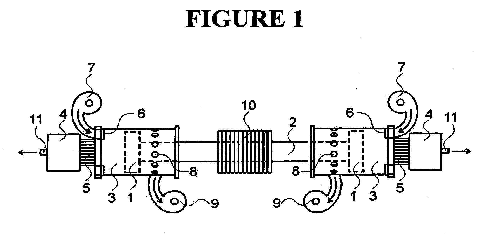
[0311]A laboratory bench scale test device utilizes a electrodynamic thruster (FIG. 1-1) two opposed aluminum cylinders (FIG. 1-3), two adsorbent contactors (FIG. 1-4) and a motion controller with Hall effect feedback. The thruster produces a 2 cm amplitude 10 cycle / second stroke. Pressure sensors located in cylinders indicate the pressure develops at each point in the cycle. The contactors (FIG. 1-4) contain about 30 mesh calcium exchanged zeolite (ZeoChem) spherical beads. Teflon™ pistons (31 mm diameter) are affixed to opposing ends of the thruster rod. Oxygen production is recorded for various cycle rates and amplitudes. Power consumption is computed as V×I.

Example

Example 2

[0312]The sorptive device may be configured to produce a high pressure product such as may be needed for coal gasification, metal cutting, or aquaculture applications. In this case, a first cylinder and piston is used to alternately adsorb and desorb a fluid component. A second piston and cylinder, having a much smaller cross section is used to compress the product or the raffinate from the first cylinder. The force to drive the second piston is taken, in part, from the expanding desorbing fluid acting on the first piston, which is directly connected in a linear manner to the second piston.

Example

Example 3

[0313]FIG. 3 illustrates a combination gas separation unit and booster compressor. Piston-cylinder arrangement 1 delivers alternating high and low pressures to adsorbent contactor 2. Gas purification occurs as described for FIG. 2 cycle. Purified gas is cooled in the heat rejection unit 3 and is delivered to booster compressor 4. Booster compressor 4 uses waste energy from the desorbed gas at 1.


PUM

PropertyMeasurementUnit
Temperatureaaaaaaaaaa
Timeaaaaaaaaaa
Volumeaaaaaaaaaa

Abstract

Methods, devices, and systems, and devices for carrying out sorption (adsorption and absorption) for separating and/or purifying fluid mixtures are disclosed. Medical oxygen generators, dehumidifying units, sorptive heat pumps, ozone generators and Peltier devices are also disclosed. The sorption methods involve pressure swing operation of at least two sorption units. Energy from the desorbing and decompressing fluid is substantially recovered and used within the system.

Description

CROSS REFERENCE TO RELATED APPLICATIONS[0001]This application claims the benefit of U.S. Application No. 60 / 798,597 filed May 5, 2006, the entire disclosure of which is incorporated herein by reference.REFERENCE TO GOVERNMENT GRANTS[0002]Portions of the disclosure herein may have been supported in part by grants from the National Science Foundation / Small Business Innovative Research Grant No. 0419821 and the National Institutes of Health / Small Business Technology Transfer Research Grant No. 1 R41 HL080825-01. The United States Government may have certain rights in this application.FIELD OF THE INVENTION[0003]The invention relates generally to methods, devices, and systems for carrying out sorption (both adsorption and absorption) processes for separating and purifying fluid mixtures and, more particularly, to methods, devices, and systems employing, inter alia, a reciprocating biaser for separation and purification processes.BACKGROUND OF THE INVENTION[0004]Adsorption is a process b...

Claims


Application Information

Patent Timeline
IPC IPC(8): B01D53/02B01D53/047B01J19/08H01L35/28F25B13/00
CPCB01D53/0438B01D53/0462B01D53/047B01D53/261B01D2259/4533B01D2257/102B01D2257/80B01D2259/40094B01D2259/402B01D2256/12
Inventor GALBRAITH, S. DOUGLAS
Owner SEPARATION DESIGN GROUP
Why Eureka
Try Eureka