
Supercritical fluid process for producing nano graphene platelets

a technology of nano graphene and supercritical fluid, which is applied in the direction of single-layer graphene, bulk chemical production, non-metal conductors, etc., can solve the problems of tedious process, inability to disperse go platelets in water or other solvents, and inability to produce nano graphene sheets through these methods. achieve good electrical conductivity

Active Publication Date: 2010-02-25
GLOBAL GRAPHENE GRP INC
View PDF19 Cites 86 Cited by
  • Summary
  • Abstract
  • Description
  • Claims
  • Application Information

AI Technical Summary

Benefits of technology

[0042]Furthermore, Kaschak, et al. [55] did not provide any evidence to show the existence of nano-scaled graphite particles that they claimed they produced with this method. In particular, they claimed that “one advantage of the invention is that the aforementioned methods may be used to manufacture graphite in a form that has a thickness of less than about 10 microns, preferably less than about 1 micron, more preferably less than about 100 nm, even more preferably less than about 10 nm, and most preferably less than about 1 nm.” However, they did not fairly suggest the conditions under which graphite particles with a thickness less than 10 nm or 1 nm could be produced. This was truly a big claim and should have been supported by solid experimental evidence; unfortunately, absolutely no evidence whatsoever was presented.
[0043]Gulari, et al. [56] proposed a method of delaminating a graphite structure with a coating agent solubilized in a supercritical fluid. According to Gulari, et al. [56], the coating agent was a polymer, monomer, or oil. The method comprises diffusing a coating agent in a supercritical fluid between layered particles of a graphite structure and catastrophically depressurizing the supercritical fluid to delaminate the coating agent-intercalated graphite particles. However, Gultari, et al. [56] failed to mention anything about the thickness of the delaminated particles. It was not clear if and how graphite platelets with a thickness less than 100 nm could be produced with this method. Gulari, et al. presumed that a coating agent was needed to prevent the reformation of the covalent bonds between graphite particles when they were broken during delamination. This is rather confusing or misleading since it is well-known that the bonding between graphite layers is van der Waals force rather than covalent bond. Furthermore, a coating agent is problematic if a pure graphene product is desired. Gulari, et al. [56] did not teach if a supercritical fluid without a coating agent solubilized therein would be capable of delaminating graphite layers. Neither Kaschak, et al. [55] nor Gulari, et al. [56] discuss the properties of the resulting exfoliated graphite.
[0044]By contrast, after an intensive research and development effort, we have found that a supercritical fluid, alone without a coating agent, was capable of both intercalating and exfoliating a graphitic material without involving an additional intercalation or oxidation step (as required in Kaschak, et al. [55]). Further, this supercritical fluid-based process is capable of producing nano graphene platelets that are ultra-thin (<10 nm) and, in many cases, thinner than 1 nm. We have also discovered that it was not necessary to discharge the supercritical fluid-intercalated graphite out of a pressure chamber to achieve graphite exfoliation. Instead, exfoliation of graphite for the NGP production could be carried out by rapidly de-pressurizing or releasing the gas from the chamber where a graphitic material was tentatively intercalated by a supercritical fluid. By keeping the exfoliated graphite or NGPs in the chamber, the chamber can be re-pressurized and then de-pressurized to further separate multi-layer NGPs. This procedure can be repeated until all or most of the NGPs are single-layered structures.
[0045]Hence, it was an object of the present invention to provide a pristine nano graphene platelet material that has good electrical conductivity.
[0046]It was another object of the present invention to provide a process for mass-producing pristine NGPs without involving the use of any undesirable chemical.
[0047]It was a further object of the present invention to provide a process for producing ultra-thin NGPs (e.g., those with a thickness less than 1 nm).References Cited

Problems solved by technology

Furthermore, the reduction procedure often involves the utilization of undesirable chemicals, such as hydrazine.
These films were exposed to a high temperature, high vacuum environment for de-oxygenation, but the resulting GO platelets were no longer dispersible in water or other solvents.
However, unless stabilized by selected polymers, the chemically modified graphene sheets obtained through these methods tend to precipitate as irreversible agglomerates due to their hydrophobic nature.
This is a very tedious process, nevertheless.(p) Another very tedious process for the preparation of GO nano sheets, proposed by Becerril, et al.
Unfortunately, Shioyama did not discuss the thickness of the isolated graphene sheets.(s) Jang, et al.
The process must be carefully conducted in a vacuum or an extremely dry glove box environment since pure alkali metals, such as potassium and sodium, are extremely sensitive to moisture and pose an explosion danger.
It is questionable if this process is easily amenable to the mass production of nano-scaled platelets.
This is a slow process that thus far has produced very small graphene sheets.
There are several major issues associated with the aforementioned processes.
These include, for instance:(1) In most of these methods of graphite intercalation and exfoliation, undesirable chemicals are used.
Consequently, a tedious washing step is required, which produces contaminated waste water that requires costly disposal steps.(2) The GO nano platelets prepared by Approach 1 exhibit an electrical conductivity typically several orders of magnitude lower than the conductivity of pristine NGPs.
However, other than the direct ultrasonication method developed by the applicants earlier [54], these processes are not amenable to large-scale production of NGPs with a reasonable cost.
[55] did not provide any evidence to show the existence of nano-scaled graphite particles that they claimed they produced with this method.
The method comprises diffusing a coating agent in a supercritical fluid between layered particles of a graphite structure and catastrophically depressurizing the supercritical fluid to delaminate the coating agent-intercalated graphite particles.
Furthermore, a coating agent is problematic if a pure graphene product is desired.

Method used


Image

  • Supercritical fluid process for producing nano graphene platelets
  • Supercritical fluid process for producing nano graphene platelets
  • Supercritical fluid process for producing nano graphene platelets

Examples


example 1

Preparation of Pristine NGPs from Natural Graphite Using CO2 Supercritical Fluids

[0149]A natural graphite sample (approximately 5 grams) was placed in a 100 milliliter high-pressure vessel. The vessel was equipped with security clamps and rings that enable isolation of the vessel interior from the atmosphere. The vessel was in fluid communication with high-pressure CO2 by way of piping means and controlled or regulated by valves. A heating jacket was wrapped around the vessel to achieve and maintain the critical temperature of carbon dioxide. High-pressure carbon dioxide was introduced into the vessel and maintained at approximately 1,100 psig (7.58 MPa). Subsequently, the vessel was heated to about 70° C. at which the supercritical conditions of carbon dioxide were achieved and maintained for about 3 hours, allowing CO2 to diffuse into inter-graphene spaces. Then, the vessel was immediately depressurized “catastrophically’ at a rate of about 3 milliliters per second. This was accom...

example 2

Repeated Intercalation and Exfoliation with CO2 Supercritical Fluids

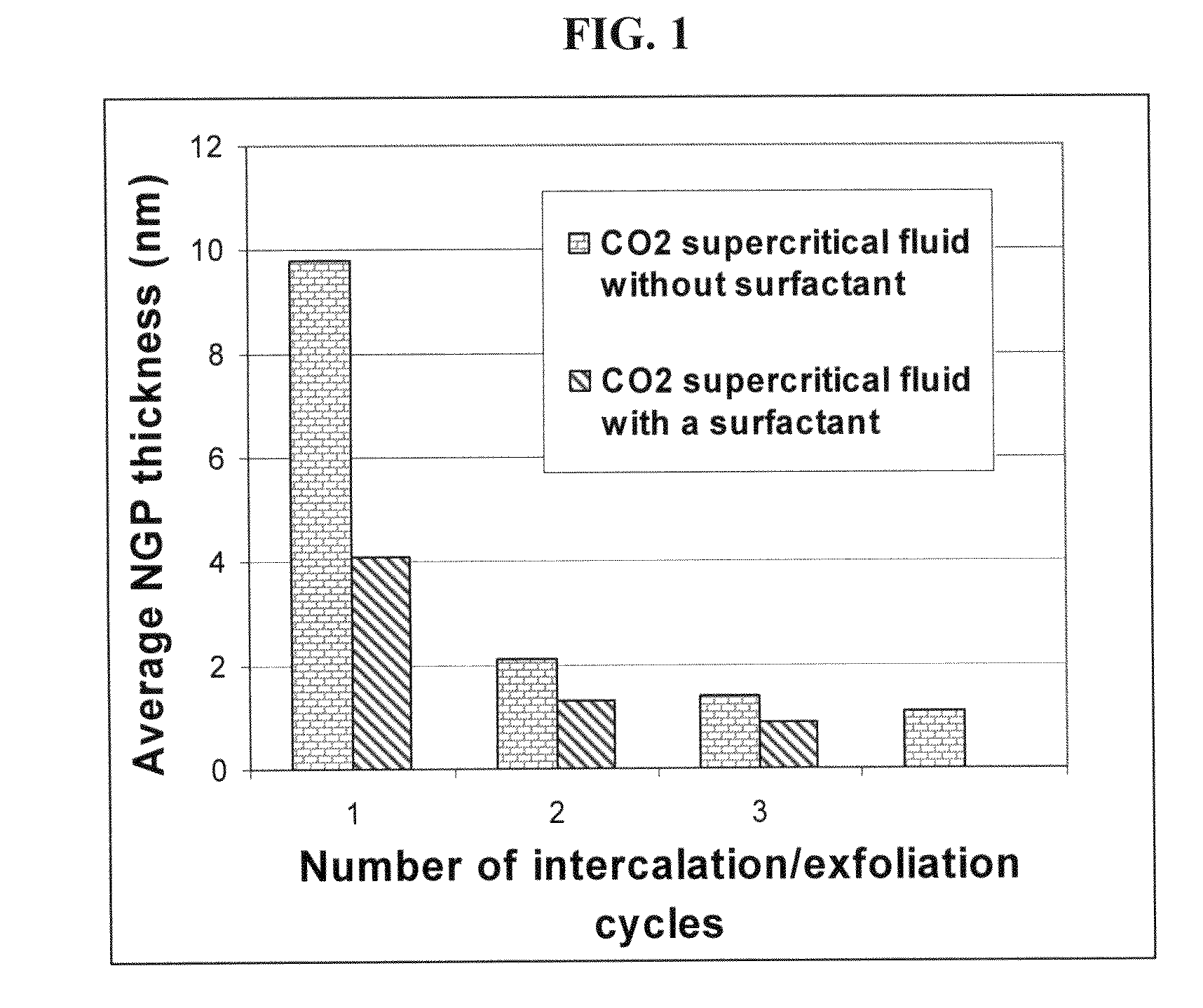
[0151]Approximately two-thirds of Sample 1-A was removed from the pressure vessel. The remaining NGPs were subjected to another cycle of supercritical CO2 intercalation and de-pressurization treatments (i.e., the above procedures were repeated with a pressure of 7.5 MPa and temperature 65° C.), yielding much thinner NGPs with an average thickness of 2.1 nm (identified as Sample 2). The specific surface area, as measured by the BET method, was approximately 430 m2 / g. TEM and AFM examinations indicated that there were many single-layer graphene sheets in this sample. The electrical conductivity of a thin film made from these ultra-thin NGPs was 1,450 S / cm.

example 3

Preparation of Pristine NGPs from Natural Graphite Using CO2 Supercritical Fluids Containing a Surfactant

[0152]Sample 3 was prepared under essentially identical supercritical CO2 conditions as Sample 1-A, with the exception that a small amount of surfactant (approximately 0.05 grams of Zonyl® FSO) was mixed with 5 grams of natural graphite before the mixture was sealed in the pressure vessel. The resulting NGPs have a surprisingly low average thickness, 4.1 nm. After the pressurization and de-pressurization procedures were repeated for two more cycles, the resulting NGPs had an average thickness less than 1.0 nm, indicating that a majority of the NGPs were single-layer or double-layer sheets. The specific surface area of this sample after a repeated cycle was approximately 900 m2 / g. It may be noted that a sample of all single-layer graphene sheets should exhibit a specific surface area of >2,670 m2 / g. It is clear that the presence of a surfactant or dispersing agent promotes separat...


PUM


Abstract

The present invention provides a process for producing pristine or non-oxidized nano graphene platelets (NGPs) that are highly conductive. The process comprises: (i) subjecting a graphitic material to a supercritical fluid at a first temperature and a first pressure for a first period of time in a pressure vessel and then (ii) rapidly depressurizing the fluid at a fluid release rate sufficient for effecting exfoliation of the graphitic material to obtain the NGP material. Conductive NGPs can be used as a conductive additive in transparent electrodes for solar cells or flat panel displays (e.g., to replace expensive indium-tin oxide), battery and supercapacitor electrodes, and nanocomposite for electromagnetic wave interference (EMI) shielding and static charge dissipation, etc.

Description

FIELD OF THE INVENTION[0001]The present invention relates generally to the field of carbon- or graphite-based nano materials, and more particularly to nano graphene platelets (NGPs).BACKGROUND OF THE INVENTION[0002]The present discussion of the prior art will make reference to the patent literature and technical papers listed at the end of this section.[0003]The nanoscale graphene platelet (NGP) or graphene nano-sheet is an emerging class of nano materials. An NGP is a nanoscale platelet composed of one or more layers of a graphene plane, with a platelet thickness from less than 0.34 nm to 100 nm. In a graphene plane, carbon atoms occupy a 2-D hexagonal lattice in which carbon atoms are bonded together through strong in-plane covalent bonds. In the c-axis or thickness direction, several graphene planes may be weakly bonded together through van der Waals forces to form a multi-layer NGP. An NGP may be viewed as a flattened sheet of a carbon nano-tube (CNT), with a single-layer NGP co...

Claims


Application Information

Patent Timeline
IPC IPC(8): H01B1/04D01F9/12
CPCB82Y30/00B82Y40/00C01B31/0469C01P2006/12C01B2204/02C01B2204/22C01B31/0476C01B32/19C01B32/192Y02P20/54
Inventor ZHAMU, ARUNAJANG, BOR Z.
Owner GLOBAL GRAPHENE GRP INC
Learn More