Optically driven actuator and method of manufacturing the same

a technology of actuators and actuators, applied in the direction of machines/engines, mechanical equipment, other domestic objects, etc., can solve the problems of unfunctional gels in dry environments, low response speed, and small contraction rate, and achieve easy manufacturing of photoresponse, enhance processability, and enhance processability

Inactive Publication Date: 2010-03-04
FUJIFILM CORP
View PDF11 Cites 10 Cited by
  • Summary
  • Abstract
  • Description
  • Claims
  • Application Information

AI Technical Summary

Benefits of technology

[0026]According to the above method of manufacturing an optically driven actuator, an optically driven actuator having enhanced processability and photoresponsivity can be easily manufactured by forming a film to enhance processability and then stretching and crosslinking the film to enhance photoresponsivity.
[0027]According to the present invention, it is possible to provide an optically driven actuator having photoresponsivity sufficient to deform reversibly and at high speed depending on optical stimulation, flexibility and light weight and being driven noiselessly and an easy and simple method of manufacturing the same.

Problems solved by technology

Thus, such gels have presented the problem of being unfunctional in the dry environment.
Such polymer materials are, however, problematic, when used as an actuator, in that they are driven only at high temperatures, their response speed is very low, and their contraction rate is very small.
However, any of the actuators of the above examples presents the problem of low speed of response to light and being able to function only in the form of a thin film because its response is largely decreased with increase in film thickness.
145 (2003) present the problem that their operating temperature or the like is limited because they are driven only in the liquid-crystal temperature range.
Further, forming a self-supporting thin film is complicated because the process includes the steps of: coating a substrate with a monomer composition; curing the resultant film by long-time exposure to visible light; and removing the cured film from the substrate.
Thus, there have been problems left unsolved in terms not only of performance, but of manufacturability.

Method used


Image

  • Optically driven actuator and method of manufacturing the same
  • Optically driven actuator and method of manufacturing the same
  • Optically driven actuator and method of manufacturing the same

Examples


example 1

Synthesis of Photoresponsive Crosslinked Polymer P-1 (Preparation of First and Second Optically Driven Actuators)

[0072]

[0073]To an aqueous solution prepared by adding 90 ml of water to 22 ml of an aqueous solution of 37% by weight hydrochloric acid, M-1 (10.91 g, 0.100 mols) was added and cooled to 5° C. or lower. To this solution, an aqueous solution prepared by dissolving 7.59 g of sodium nitrite in 22 ml of water was added dropwise (internal temperature was 5° C. or lower). The mixed solution was stirred for 30 minutes while keeping the internal temperature at 5° C. to 10° C. The resultant solution was added dropwise to a solution of M-2 (15.02 g, 0.100 mol) in an aqueous solution of sodium hydroxide (sodium hydroxide: 16.12 g, water: 90 ml), while keeping the internal temperature at 5° C. or lower, and the mixed solution was stirred for 30 minutes. The resultant reaction product was added to an aqueous solution of 1 N hydrochloric acid (1.5 L), and the produced precipitate was f...

example 2

Synthesis of Photoresponsive Crosslinked Polymer P-12 (Preparation of Third, Fourth and Fifth Optically Driven Actuators)

[0078]

[0079]First, M-3 (2.703 g, 10 mmols) was dissolved in an aqueous solution of sodium hydroxide (sodium hydroxide: 0.81 g, water: 100 ml), and to the resultant solution, tetra-n-butylammonium chloride (1.60 g, 5.76 mmols) was added. Then, a solution prepared by dissolving M-4 (0.27 g, 1.5 mmols) and M-6 (1.79 g, 8.5 mmols) in 1,2-dichloroethane (30 ml) was added dropwise over 30 minutes, while vigorously stirring the M-3 solution, and stirred vigorously for another 30 minutes. To the resultant reaction product, 20 ml of methylene chloride was added so as to separate the organic layer. The separated organic layer was then washed with an aqueous solution of saturated sodium chloride and dried by adding magnesium sulfate. The solvent was distilled away to some extent to concentrate the organic layer, and the concentrated organic layer was added to methanol to be ...

example 3

Evaluation of Photoresponsivity for First, Third and Fifth Optically Driven Actuators

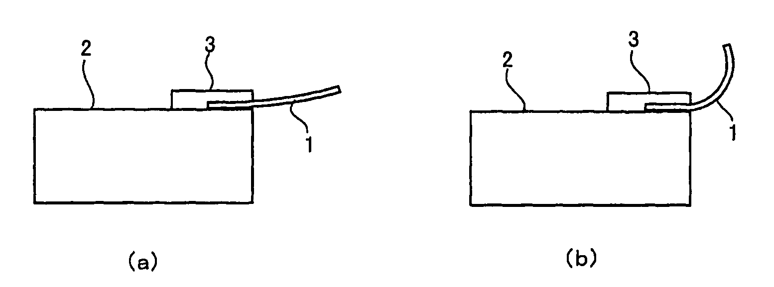
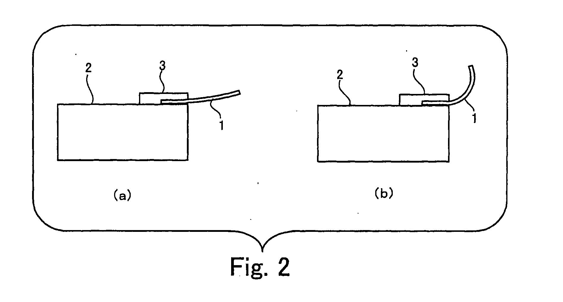
[0084]FIG. 2 is a diagram illustrating the evaluation experiment of photoresponsivity for the first optically driven actuator of Example 3 of the present invention.

[0085]Part (a) of FIG. 2 illustrates the state of the optically driven actuator before exposed to ultraviolet light. One end of the optically driven actuator 1 was fixed on the edge of the top surface of the stand 2 with clamps 3. The clamps 3 are made up of materials that intercept light.

[0086]Ultraviolet light of an intensity of 100 mW / cm2 (365 nm) emitted an ultraviolet irradiator (EXECURE 3000, manufactured by HOYA CANDEO OPTRONICS) was applied to the first optically driven actuator 1 directly from above at room temperature.

[0087]Part (b) of FIG. 2 illustrates the state of the optically driven actuator 1 after ultraviolet radiation. As shown in part (b) of FIG. 2, the optically driven actuator 1 in the uniaxial stretching direction ch...


PUM

PropertyMeasurementUnit
optical stimulationaaaaaaaaaa
sizeaaaaaaaaaa
weightaaaaaaaaaa

Abstract

An optically driven actuator includes a crosslinked polymer obtained by crosslinking at least part of the side chains of a condensation polymer having, on its backbone chain, a photoisomerizable group that undergoes structural change under optical stimulation. The crosslinked polymer deforms reversibly depending on optical stimulation, thereby performing the function of an actuator.

Description

TECHNICAL FIELD[0001]The present invention relates to an optically driven actuator that deforms under optical stimulation and a method of manufacturing the same.BACKGROUND ART[0002]There have been increasing demands in the fields of medical instruments, industrial or personal robots, micromachines, etc. for small size, light-weight and flexible actuators.[0003]Polymer actuators in particular have attracted considerable attention because of their flexibility, light weight, and noiselessness at the time of being driven. Of the polymer actuators, optically driven actuators that are driven by light are capable of supplying energy in a non-contact manner, do not need wiring for driving and are capable of eliminating noises generated in electric wiring, and therefore, their application particularly to industrial robots or micromachines used in the medical / nursing fields or aerospace field has been expected.[0004]Studies on photoresponsive gels, as polymer materials that are driven under o...

Claims


Application Information

Patent Timeline
Patent Type & Authority Applications(United States)
IPC IPC(8): B29D7/01C08F20/00
CPCC07C245/08F03G7/005C08J2300/12C08J5/18
Inventor YASUDA, TAKAYASUNISHIKAWA, NAOYUKI
Owner FUJIFILM CORP
Why Eureka
Try Eureka