Electromagnetic wave/particle beam spectroscopic method and electromagnetic wave/particle beam spectroscopic instrument

a technology of electromagnetic waves and particle beams, applied in the field of electromagnetic waves/particle beam spectroscopic methods and electromagnetic waves/particle beam spectroscopic instruments, can solve the problems of difficult to capture all of the characteristic x-rays emitted from one kind of atom, spectroscopic methods and instruments, and high counting rate cannot be easily realized, so as to ensure performance

Inactive Publication Date: 2010-03-11
INTER UNIV RES INST NAT INST OF NATURAL SCI
View PDF0 Cites 6 Cited by
  • Summary
  • Abstract
  • Description
  • Claims
  • Application Information

AI Technical Summary

Benefits of technology

[0008]It is an objective of the present invention to provide an electromagnetic wave / particle beam spectroscopic method that can capture wide measurement ranges of high counting rates and energy levels without limiting the number of measurement-target electromagnetic waves or particle beams incident upon the photo-receptive element. It is another objective of the present invention to provide an electromagnetic wave / particle beam spectroscopic method that is not easily deteriorated in spectroscopic capability and are resistant to electromagnetic noise, vibrations, heavy sound, heat and specific particle beams of interest, particle beams other than electromagnetic waves, electric noise due to electromagnetic waves, mechanical destruction, and recoiling of solid constituent atoms and also more resistant to radiation exposure on the detection means than the conventional energy resolving technologies.
[0073]In such a manner, the present invention reliably ensures performance of the conventional semiconductor detectors, superconducting detectors and crystals, and diffractive gratings without a need of maintenance, even in an environment in which the operations or the performance of the conventional semiconductor detectors, superconducting detectors and crystals, and diffractive gratings. Accordingly, the present invention is greatly expected as an electromagnetic wave / particle beam spectroscopic method for use in high temperature plasma fusion experiments to be conducted in the future.

Problems solved by technology

For these reasons, there is a problem that a high counting rate cannot be realized easily in the case of pulse height analysis and the superconducting detectors.
Further, the diffractive grating and the dispersive crystal have a high dispersive power as well as a good energy resolution, but have very small measurement range conversely and find it difficult to capture all of the characteristic X-rays emitted from one kind of atoms.
The conventional spectroscopic methods and instruments have also a problem that their spectroscopic capability is easily deteriorated unless they shield the detection means against radiation exposure and block off electromagnetic noise, vibrations, heavy sound, heat and specific particle beams of interest, particle beams other than electromagnetic waves, electric noise due to electromagnetic waves, mechanical destruction, and recoiling of solid constituent atoms, because they are not resistant to these.

Method used


Image

  • Electromagnetic wave/particle beam spectroscopic method and electromagnetic wave/particle beam spectroscopic instrument
  • Electromagnetic wave/particle beam spectroscopic method and electromagnetic wave/particle beam spectroscopic instrument
  • Electromagnetic wave/particle beam spectroscopic method and electromagnetic wave/particle beam spectroscopic instrument

Examples


first embodiment

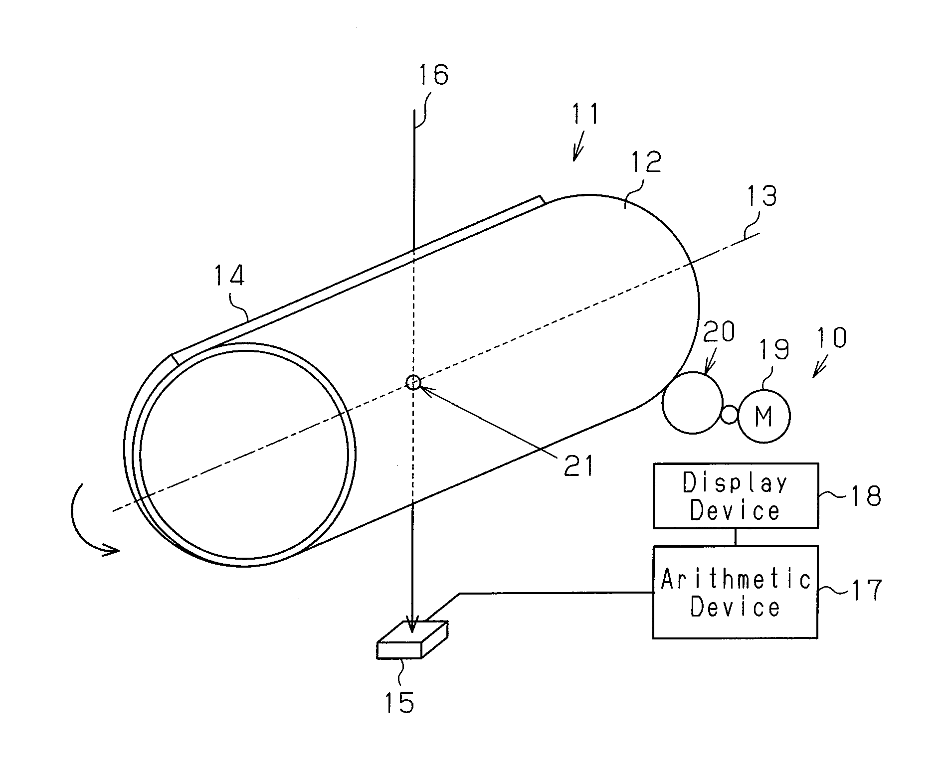
[0097]A description will be given, with reference to FIG. 1, of the first embodiment in which an electromagnetic wave / particle beam spectroscopic method and an electromagnetic wave / particle beam spectroscopic instrument of the present invention are embodied. Hereinafter, the electromagnetic wave / particle beam spectroscopic instrument is referred to as a spectroscopic instrument simply.

[0098]As shown in FIG. 1, a spectroscopic instrument 10 comprises a Laplace transform filter 11, a detection element 15 as detection means, an arithmetic device 17 as inverse Laplace transform means, and a display device 18 as display means. The detection element 15 is disposed on the other side of the Laplace transform filter 11 with respect to a light source. In the present embodiment, the detection element 15 can detect an X-ray.

[0099]The Laplace transform filter 11 comprises a cylindrical base body 12 and an attenuation body 14 vapor-deposited on half the circumferential surface of the base body 12...

second embodiment

[0138]Since the present embodiment employs almost the same hardware configuration as the first embodiment, identical reference numerals are given to identical components.

[0139]The second embodiment involves obtaining polarized components of an incident spectrum in a case where the absorption coefficient of an attenuation body exhibits dependency on the polarization of an electromagnetic wave or a particle beam.

[0140]Linear polarization of light comes in vertical polarization and horizontal polarization with respect to a light progressing direction, that is, with respect to an optical axis as shown in FIG. 19, and its components can be measured as polarization. Further, in the case of circular polarization of light, there are, as shown in FIG. 20, clockwise polarization and counterclockwise polarization about the light progressing direction, that is, about the optical axis, and the clockwise and counterclockwise components can be measured as polarization. In the case of particle beam...

application example

[0158]An application example will be described with reference to FIGS. 8 to 11.

[0159]The application example includes measurement of an X-ray in large helical device in the National Institute for Fusion Science. FIG. 8 is a schematic layout of the spectroscopic instrument 10 for the purpose of evaluating the transport of impurity particles. Identical reference numerals are given to the same components as the first embodiment. In the application example, a one-dimensional semiconductor array, namely, a one-dimensional multi-element type detector is employed as the detection element 15. Reference numeral 22 in the figure indicates a storage device connected to the arithmetic device 17.

[0160]Plasma in Large Helical Device (not shown) has a high emissivity of characteristic X-rays, so that if the one-dimensional multi-element type detector of the detection element 15 is used as a spectroscopic instrument 10, it is possible to have the energy resolution, the space resolution, and the tim...


PUM


Abstract

The present invention provides an electromagnetic wave / particle beam spectroscopic instrument that is not easily deteriorated in spectroscopic capability, and is resistant to electromagnetic noise, vibrations, heavy sound, heat and specific particle beams of interest, particle beams other than electromagnetic waves, electric noise due to electromagnetic waves, mechanical destruction, and recoiling of solid constituent atoms and is also more resistant to radiation exposure on the detection means than the conventional energy resolving technologies. A spectroscopic instrument 10 includes a Laplace transform filter 11 that performs Laplace transform on the intensity of an incident spectrum, a detection element 15 that detects a transmitted intensity of the incident spectrum, and an arithmetic device 17 that performs inverse Laplace transform on the detected transmitted intensity of the incident spectrum, thereby calculating the incident intensity of the incident spectrum that has entered the Laplace transform filter 11.

Description

TECHNICAL FIELD[0001]The present invention relates to an electromagnetic wave / particle beam spectroscopic method and an electromagnetic wave / particle beam spectroscopic instrument.BACKGROUND ART[0002]The conventional spectroscopic methods having a predetermined energy resolution apply the electronic excitation of solids or the interference effect of light by use of electromagnetic waves or particle beams. Based on these principles, the industries have already practically used a pulse height analyzer, a superconducting detector, a dispersive crystal, and a diffractive grating.[0003]So-far developed energy discrimination methods by use of the current semiconductor detector and the like receive at most one photon or particle within a discrimination lapse of time of its circuit system and convert the energy of the received photon or particle into electron pulses, thus detecting its wave height value. That is, in the case of pulse height analysis, the count rate is determined by the proc...

Claims


Application Information

Patent Timeline
Patent Type & Authority Applications(United States)
IPC IPC(8): G01T1/36
CPCG01T1/36G01T1/2985G01J3/28
Inventor MUTO, SADATSUGU
Owner INTER UNIV RES INST NAT INST OF NATURAL SCI
Why Eureka
Try Eureka