Coating Liquid, Conductive Film Formed By Coating Liquid, and Forming Method Thereof

a technology of coating liquid and conductive film, which is applied in the direction of liquid/solution decomposition chemical coating, non-metal conductors, physical/chemical process catalysts, etc., can solve the problems of low formation rate, large amount of energy required to form a film, and difficulty in maintaining vacuum, etc., to achieve excellent adhesion to a base plate, high hardness, and high transparency

Inactive Publication Date: 2010-03-11
CENTRAL JAPAN RAILWAY COMPANY
View PDF1 Cites 2 Cited by
  • Summary
  • Abstract
  • Description
  • Claims
  • Application Information

AI Technical Summary

Benefits of technology

[0016]In the above-described technique (ii), since some tens to some hundreds times of spraying are normally required to attain low resistivity, time efficiency of the process is lowered.
[0064]In the conductive film covered product according to the present invention, the conductive film does not have cracks formed thereon, has high degree of hardness, and has an excellent adhesiveness to a base plate. Moreover, a conductive film according to the present invention is flat, smooth, and has high transparency. Therefore, in a case, for example, wherein a base plate is a glass, the transparency of the glass can be maintained. In a case wherein a base plate is a mirror, the reflectivity of the mirror can be maintained. Furthermore, since the conductive film according to the present invention does not have to contain a binder, the concentration of In oxide, Sn oxide or In—Sn oxide, contained in the formed film, is not diluted by a binder, and the effect of In oxide, Sn oxide or In—Sn oxide (for example, conductive effect) is high.

Problems solved by technology

However, in a gas-phase method such as sputtering, there are problems in that large-sized equipments are required, it is not easy to maintain vacuum when forming a film having a large area, and a large quantity of energy is required to form a film.
Furthermore, there are other problems such as lower formation rate, and low use efficiency of raw materials caused by low efficiency of target use.

Method used


Image

  • Coating Liquid, Conductive Film Formed By Coating Liquid, and Forming Method Thereof
  • Coating Liquid, Conductive Film Formed By Coating Liquid, and Forming Method Thereof
  • Coating Liquid, Conductive Film Formed By Coating Liquid, and Forming Method Thereof

Examples


embodiments

[0068]The present invention is described based on embodiments.

(a) Producing Metal Complexes

[0069]A solution was prepared wherein an amount indicated in Table 1 of Compound A shown in Table 1 below was dissolved in a suitable amount of solvent (xylene). In the solution, respective amount indicated below of indium acetate and tin(IV)butoxide, finely crushed in a mortar, (tin butoxide was dropped) was blended. The blended liquid was refluxed for 1 hour, and then distilled at 132° C. until the amount of the blended liquid became half. Then volatile component of the residual blended liquid was evaporated under reduced pressure using a rotary evaporator. The residual solid content was further heated to 100° C. under vacuum using a vacuum drier so as to remove the residual volatile component thoroughly. A yield of each of the solid contents is shown in Table 1.

[0070]Even after the solid content was kept for 6 months or more, chemical change was not observed. Even though coating was perform...


PUM

PropertyMeasurementUnit
temperatureaaaaaaaaaa

Abstract

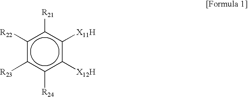
The present invention provides a technology related to a conductive film which is high in transparency, conductivity, and adhesiveness to a base plate. The present invention also provides a coating liquid including metal materials reacting with a ligand represented by Chemical Formula 1 and including indium (In), tin (Sn), or both thereof.Each of R21—R24 in the Chemical Formula 1 is one of the followings (1)-(11) and X11 and X12 is either hetero atoms or carboxylic acid.(1) a group represented by ClH2l+1 (aforementioned l is an integral number of 0 to 4),(2) a group represented by CmH2m (aforementioned m is an integral number of 2 to 4),(3) a group represented by CnH2n−1 (aforementioned n is an integral number of 2 to 4),(4) a group represented by COOR (aforementioned R is CpH2p+1 (aforementioned p is an integral number of 0 to 4) or a group represented by R═C6H5),(5) a group represented by aldehyde, ketones, COCqH2q+1 (aforementioned q is an integral number of 0 to 4), or benzophenone,(6) hydroxyl (OH) or ethers,(7) amine (NH2) or alkylamine,(8) amide(9) halogens(10) nitrile (CN)(11) nitro (NO2)

Description

TECHNICAL FIELD[0001]The present invention is related to a coating liquid used for forming a conductive film, a conductive film, a forming method thereof, and a product having a conductive film formed on a surface of the product.BACKGROUND ART[0002]A conductive film is applied in a wide rage of fields.[0003]Especially in fields related to displays, a conductive film is now essential for most display units such as a Plasma Display Panel (PDP), a Liquid Crystal Display (LCD) and an Organic Light Emitting Diode (OLED) display.[0004]In application to these display related units, a gas-phase method, such as sputtering, is most commonly used, since a film formed by a gas-phase method is dense and accordingly low in resistivity as well as excellent in uniformity.[0005]However, in a gas-phase method such as sputtering, there are problems in that large-sized equipments are required, it is not easy to maintain vacuum when forming a film having a large area, and a large quantity of energy is r...

Claims


Application Information

Patent Timeline
Patent Type & Authority Applications(United States)
IPC IPC(8): B32B9/04B05D5/12H01B1/12
CPCB01J21/066B01J37/0219C01G23/053C23C18/1279C23C18/1216C23C18/1225C09C1/3607Y10T428/31678C01B13/14C01G23/04C09D1/00C23C18/12C01P2002/84
Inventor CORDONIER, CHRISTOPHERSHICHI, TETSUYANUMATA, TAKAFUMIKATSUMATA, KENICHINAKAMURA, AKIMASAKATSUMATA, YASUHIROKOMINE, TERUOAMEMIYA, KENICHIROUYAMASHITA, MAKOTOFUJISHIMA, AKIRA
Owner CENTRAL JAPAN RAILWAY COMPANY
Why Eureka
Try Eureka