
Method of polishing amorphous/crystalline glass to achieve a low rq & wq

Inactive Publication Date: 2010-03-11
SEAGATE TECH LLC
View PDF7 Cites 20 Cited by
  • Summary
  • Abstract
  • Description
  • Claims
  • Application Information

AI Technical Summary

Benefits of technology

[0008]The embodiments of the invention relate to method of polishing at least one surface of a glass ceramic substrate including an amorphous glass portion and a crystalline portion to reduce surface roughness of the at least one surface, the method comprising at least one step of polishing the at least one surface using a polishing pad and an abrasive polishing slurry, the polishing slurry comprising a first concentration of Ceria particulates and a second concentration of Silica particulates, wherein the amorphous glass portion and the crystalline portion of the at least one surface are polished substantially equally.

Problems solved by technology

However, poor mechanical and tribological performance, track mis-registration (“TMR”), and poor flyability have been particularly problematic in the case of polymer-based substrates fabricated as to essentially copy or mimic hard disk design features and criteria.
However, the extreme difficulties encountered with grinding and lapping of glass, ceramic, and glass-ceramic composite materials have limited their use to only higher cost applications, such as mobile disk drives for “notebook”-type computers.
Although the bulk properties of glass-ceramics are ideal for substrate disks, historically, there has been no successful method for polishing the surface of the disks to meet the requirements for magnetic media storage with respect to waviness and roughness.
However, these large particulates simultaneously cause scratches and crevices in the softer amorphous portion of the substrate.
On the other hand, prior art slurries that are successful at polishing the amorphous glass are not abrasive enough to polish the crystal portions.
The use of such slurries results in crystal structures protruding from the amorphous matrix at the surface of the substrate.
Thus polishing methods using either of the prior art slurries do not provide substrate surfaces with adequate capability for current disk drive technology and requirements, particularly with respect to substrate micro-roughness, waviness, and uniformity.

Method used


Image

  • Method of polishing amorphous/crystalline glass to achieve a low rq & wq
  • Method of polishing amorphous/crystalline glass to achieve a low rq & wq
  • Method of polishing amorphous/crystalline glass to achieve a low rq & wq

Examples


examples

[0039]To demonstrate the effects of the inventive polishing method on surface roughness, the processes and compositions of two samples that were polished in accordance with the present invention and then evaluated using an atomic force microscope are presented in the following. Both samples were formed of Ohara glass and included 45-55 percent crystalline structure surrounded by a glass matrix. To produce the polished samples both were first polished for 35 minutes using a slurry comprising 29 percent volume of Ceria particulates having a 0.2-0.4 μm size. Subsequently, the surface of the samples were subjected to a final polish for 18 minutes in accordance with the invention. The polishing slurry used in the final polish was comprised of 24% Sg18R CeO2, 20% 682 SiO2, 2% Vector HTN (Triethanolamine lubricant,pH stabililizers & defoamer additives) and a remainder of de-ionized H2O.

[0040]Following the polishing method the samples were examined to determine the surface characteristics o...


PUM

PropertyMeasurementUnit
Fractionaaaaaaaaaa
Fractionaaaaaaaaaa
Fractionaaaaaaaaaa

Abstract

A method of polishing to reduce surface roughness of at least one surface of a glass ceramic substrate that includes an amorphous glass portion and a crystalline portion. The method comprises at least one step of polishing the surface using a polishing pad and an abrasive polishing slurry. The polishing slurry comprises a first concentration of Ceria particulates and a second concentration of Silica particulates. The amorphous glass portion and the crystalline portion of the at least one surface are polished substantially equally.

Description

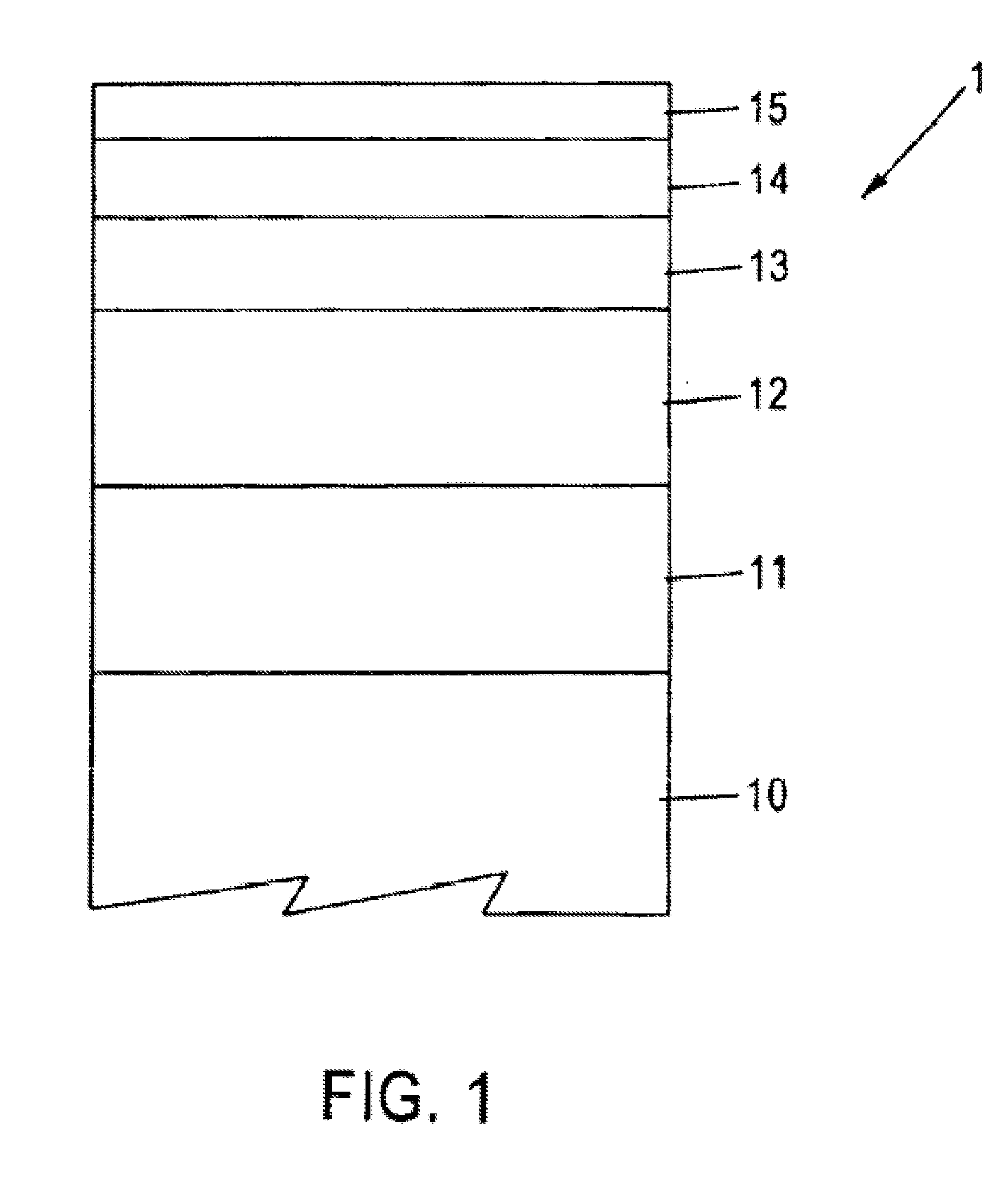
BACKGROUND OF THE INVENTION[0001]Magnetic recording media are widely used in various applications, particularly in the computer industry. A portion of a recording medium 1 utilized in disk form in computer-related applications is schematically depicted in FIG. 1 and comprises a non-magnetic substrate 10, of metal, e.g., an aluminum-magnesium (Al—Mg) alloy, having sequentially deposited thereon a plating layer 11, such as of amorphous nickel-phosphorus (NiP), a polycrystalline underlayer 12, of chromium (Cr) or a Cr-based alloy, a magnetic layer 13, e.g., of a cobalt (Co)-based alloy, a protective overcoat layer 14, containing carbon (C), e.g., diamond-like carbon (“DLC”), and a lubricant topcoat layer 15, of a perfluoropolyether compound applied by dipping, spraying, etc.[0002]In operation of medium 1, the magnetic layer 13 can be locally magnetized by a write transducer or write head, to record and store data / information. The write transducer creates a highly concentrated magnetic ...

Claims


Application Information

Patent Timeline
IPC IPC(8): G11B5/73G11B5/62B24B1/00B24B7/22
CPCB24B37/042G11B5/8404G11B5/7315G11B5/73921
Inventor BERESFORD, IANBABCOCK, ROBERT LLOYD
Owner SEAGATE TECH LLC
Features
  • Generate Ideas
  • Intellectual Property
  • Life Sciences
  • Materials
  • Tech Scout
  • Unparalleled Data Quality
  • Higher Quality Content
  • 60% Fewer Hallucinations
Learn More