Membranes and devices for gas separation

a membrane and gas separation technology, applied in the direction of membranes, separation processes, membranes, etc., can solve the problems of limited use of membrane systems, low volumetric density of hydrogen, and inability to immediately commercialize, etc., to achieve high flux, improve mechanical resistance, and high resistance

Inactive Publication Date: 2010-03-25
CENT NAT DE LA RECHERCHE SCI
View PDF12 Cites 40 Cited by
  • Summary
  • Abstract
  • Description
  • Claims
  • Application Information

AI Technical Summary

Benefits of technology

[0016]Advantages of some embodiments include the fact that these embodiments can be highly resistant to thermal shocks, environmentally friendly, and offer high fluxes and promising CO2 separation factors. The suitability of this material, and the technico-economical feasibility of the solution proposed in terms of energy economy and CO2 emission reduction in case of heavy vehicles (>3500 kg) will be exposed. We also address the main improvements in terms of membrane flux and selectivity that are accomplished to design an optimized a unit for in situ CO2 capture and liquefaction in heavy vehicles.
[0017]Nanocomposite MFI / ceramic fibres might offer several advantages compared to conventional film-like zeolite membranes. In the nanocomposite architecture, the active phase is not made of a film on the top of a porous support, but rather embedded into the support pores via pore-plugging synthesis. This not only allows individual membrane defects not to exceed the size of the support pores, but also provides a better mechanical resistance, as well as a higher resistance to thermal shocks. Moreover, the thermal behaviour of nanocomposite membranes prepared so far differs from their film-like counterparts.
[0018]The characteristics mentioned above, all eventually translating into cost for the final application, make nanocomposite MFI / ceramic fibres ideal candidates for carbon dioxide separation, for which MFI has shown to be perm selective in certain conditions. The supports used (1.7 mm diameter) can be larger than common polymeric hollow fibres. However, ceramic membranes show higher permeance together with higher thermal and mechanical stability. Moreover, the cost of the starting support, because of its symmetrical structure, would not be a limiting factor.

Problems solved by technology

The use of these systems is, however, limited due to the insufficient storing capacity of accumulators, and to the technical complexity of on-board electrical production.
Despite the seductive character of fuel cells, their commercialization does not seem to be immediate.
Indeed, their exorbitant costs, as much as 6000-8000 / km compared to those of thermal engines (about 30-50 / km), as well as the extremely low volumetric density of hydrogen, make it difficult to devise a large-scale implementation of fuel cells in vehicles before the horizon 2020.
In light of all the above stated considerations, hardly any alternative technology to conventional thermal systems relying on the liquid-fuel combustion appears to be competitive at short and mid terms for propulsion in vehicles.
Therefore, they are not expected to contribute much at short-term to the mitigation of CO2 emissions by mobile sources.
Nevertheless, none of technologies appear to be suitable for CO2 capture in mobile sources due to their high-energy costs (>4 GJ / tm CO2 removed for amine adsorption), and their large space requirements.
“Preparation of zeolite membranes of the inner surface of ceramic tubes and capillaries”, Sep. Purif. Technol. 32 (2003), 133, published a work based on ‘capillaries’ (i.e. tubes of about 4 mm diameter), with single gas permeances around 0.5 μmol·m−2·s−1·Pa−1, but no quality testing was provided further, making it very difficult to assess for membrane quality.

Method used


Image

  • Membranes and devices for gas separation
  • Membranes and devices for gas separation
  • Membranes and devices for gas separation

Examples


Embodiment Construction

Experimental

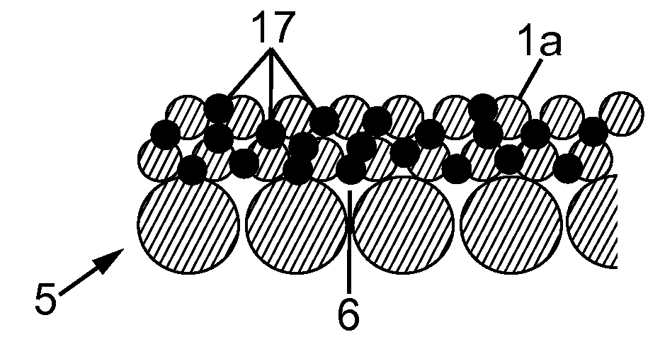
[0043]Ceramic Support

[0044]Ceramic hollow fibres can be manufactured by a wet spinning process, such as, for example, described in Goldbach and al., “Keramische Hohlfaser-und Kapillamembranen”, Keram. Z. 53 (2001) 1012, enclosed hereby by reference.

[0045]Alumina particles (SUMITOMO α-Al2O3, mean particle size: 0.33 μm) were mixed with a solution of Polysulfone (SOLVAY UDEL P-3500) in N-Methylpyrrolidone (MERCK) and were ball-milled for 16 h. This slurry was spun through a spinneret into a water bath where the polymer precipitated incorporating the ceramic particles. The resulting green fibres were cut into 30-cm pieces and sintered to full ceramic hollow fibres. The properties of the final fibres are summarized in Table 1.

TABLE 1Properties of the ceramic hollow fibres used assupports for zeolite membrane synthesis in this workMean outer diameter1.65mmMean wall thickness230μmMechanical stability (3-point bending test)112MPaPorosity43%First bubble point2.5bara

[0046]Only ho...


PUM


Abstract

A membrane includes:
    • a hollow support having a plurality of pores
    • an active phase including a gaz-selective capting material embedded into the pores.

Description

BACKGROUND OF THE INVENTION[0001]Carbon dioxide (CO2) is regarded as one of the main promoters for climate change, accounting itself for ca. 70% of the gaseous radiative force responsible for anthropogenic greenhouse effect. Fossil fuel burning for energy production (electricity and heat) is the first world CO2 emission source, reaching the level of 25000 MtmCO2 / year in 2003. According to the IEA-OCDE estimates, this sector accounted itself for 35% of world CO2 emissions in 2002, with an annual increase about +33% in the period 1990-2002. The second sector in terms of CO2 emissions is transport, involving 24% of the world emissions (2002) and showing a rapid increase in the last decade due to the increase of the automobile park.[0002]This profile is, however, inversed in the case of France (see FIG. 1 showing CO2 emissions in France per sector). As has been recently pointed out in an exhaustive report from the French Parliament and Senate, this ‘French specificity’ is mainly attribu...

Claims


Application Information

Patent Timeline
Patent Type & Authority Applications(United States)
IPC IPC(8): B01D53/02B05D3/00
CPCB01D53/228B01D53/92B01D67/0051B01D67/0083B01D69/08B01D69/10B01D2325/24B01D71/028B01D2257/504Y02C10/08Y02C10/10B01D2323/24B01D2325/02B01D69/141Y02C20/40
Inventor MIACHON, SYLVAINALSHEBANI, AWADPERA-TITUS, MARCDALMON, JEAN-ALAINLEMEULLE, SYLVIEMIACHON-LEMEULLE, MAEMIACHON-LEMEULLE, TELIO
Owner CENT NAT DE LA RECHERCHE SCI
Why Eureka
Try Eureka