Method for passivating exposed copper surfaces in a metallization layer of a semiconductor device

a technology of metallization layer and copper surface, which is applied in the direction of semiconductor/solid-state device manufacturing, basic electric elements, electric devices, etc., can solve the problems of copper not being efficiently applied onto the substrate at practical deposition, the metallization layer entails a number of layers, and the copper also exhibits a number, so as to reduce the overall process complexity, and enhance the surface passivation degree

Active Publication Date: 2010-04-01
ADVANCED MICRO DEVICES INC
View PDF8 Cites 7 Cited by
  • Summary
  • Abstract
  • Description
  • Claims
  • Application Information

AI Technical Summary

Benefits of technology

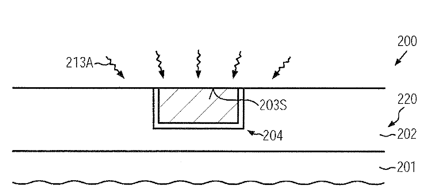
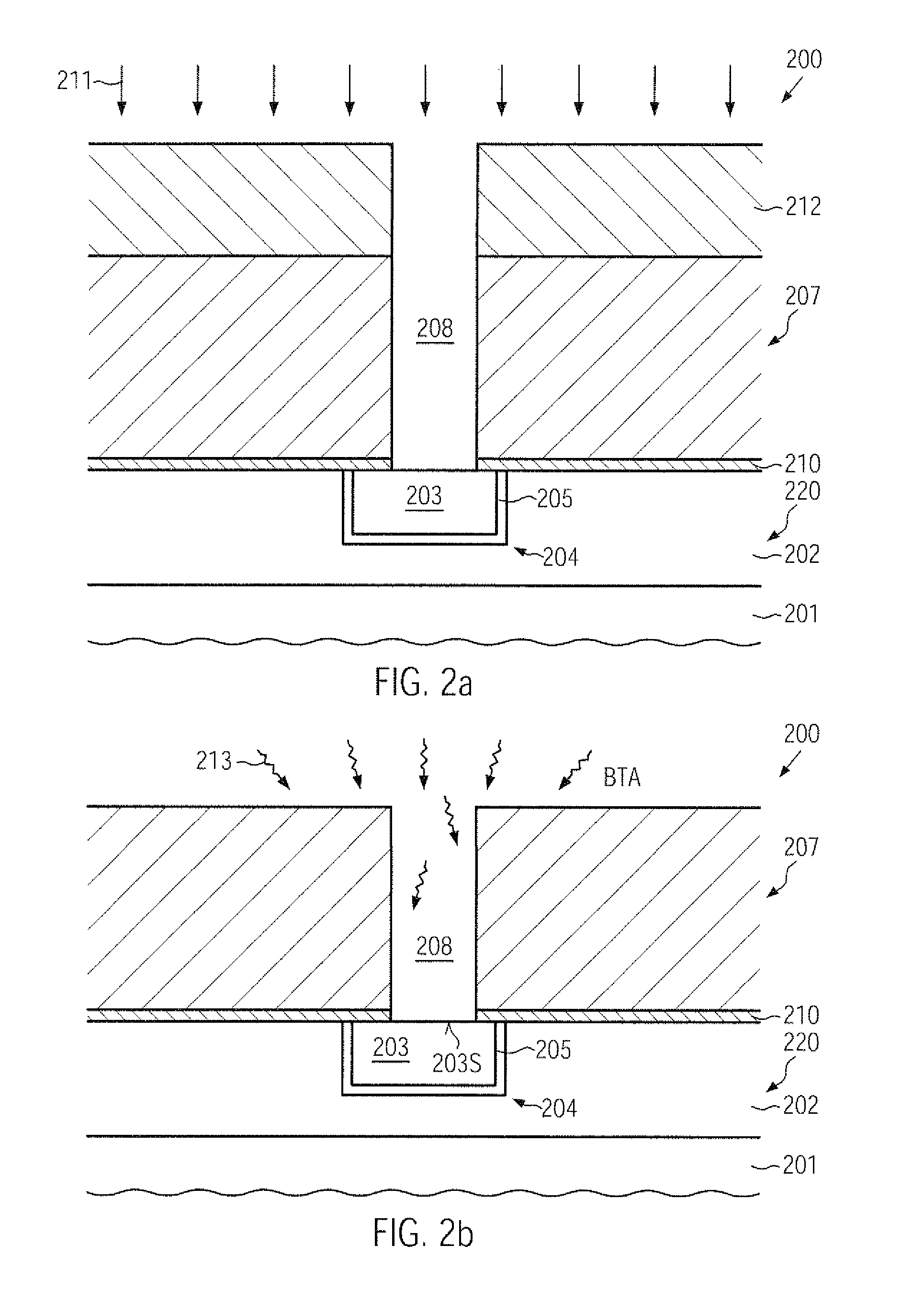
[0014]Generally, the present disclosure relates to techniques for forming sophisticated metallization systems of semiconductor devices while reducing overall process complexity associated with the surface preparation of sensitive metal regions, such as copper-containing metal surfaces, in that an enhanced degree of surface passivation may be provided without requiring highly aggressive wet chemical etch steps, which may conventionally be the reason for material degradation of sensitive dielectric materials and the like, as previously discussed. The present disclosure contemplates a treatment of sensitive exposed metal surface areas on the basis of a vaporized chemical agent, such as a corrosion hindering agent, which may be applied in an appropriate low pressure ambient. For instance, in some illustrative embodiments disclosed herein, the metal surface may be exposed to the low pressure vapor phase ambient immediately after removing material from the initially covered metal surface, wherein, based on the vaporized state of the corrosion hindering agent, an enhanced degree of surface passivation may be accomplished, substantially without significantly negatively affecting other dielectric surface areas. Thus, any further process steps may be performed on the basis of a passivated surface portion, thereby enabling a highly efficient overall manufacturing flow in which wet chemical aggressive cleaning steps may be omitted, according to some illustrative embodiments disclosed herein. Hence, in this case, overall process complexity may be reduced since dedicated wet chemical cleaning tools may no longer be required, while, in some embodiments, the corresponding low pressure vapor phase ambient may effectively be established without requiring additional transport activities of the substrate or even without exposing the substrate to ambient atmosphere.

Problems solved by technology

Due to the large number of circuit elements and the required complex layout of the integrated circuits, generally, the electrical connection of the individual circuit elements may not be established within the same level on which the circuit elements are manufactured, but requires one or more additional “wiring” layers, also referred to as metallization layers.
The fabrication of a plurality of metallization layers entails extremely challenging issues to be solved, such as providing the mechanical, thermal and electrical reliability of a plurality of stacked metallization layers that may be employed on sophisticated microprocessors.
Despite these advantages, copper also exhibits a number of disadvantages regarding the processing and handling of copper in a semiconductor facility.
For instance, copper may not be efficiently applied onto a substrate at practical deposition rates by well-established deposition methods, such as chemical vapor deposition (CVD), and also may not be effectively patterned by the usually employed anisotropic etch procedures.
A further major drawback of the use of copper is its propensity to readily diffuse in many dielectric materials, such as silicon dioxide, which is a well-established and approved dielectric material in fabricating integrated circuits.
Hence, complex barrier technologies are required to support further device scaling, wherein the usage of dielectric materials with reduced permittivity may even impart further restrictive constraints to the barrier layer, and also to preparation of exposed copper surfaces prior to applying the barrier materials, since copper readily reacts with oxygen and other reactive components, such as fluorine, sulfur and the like, which may be present in traces in the clean room ambient.
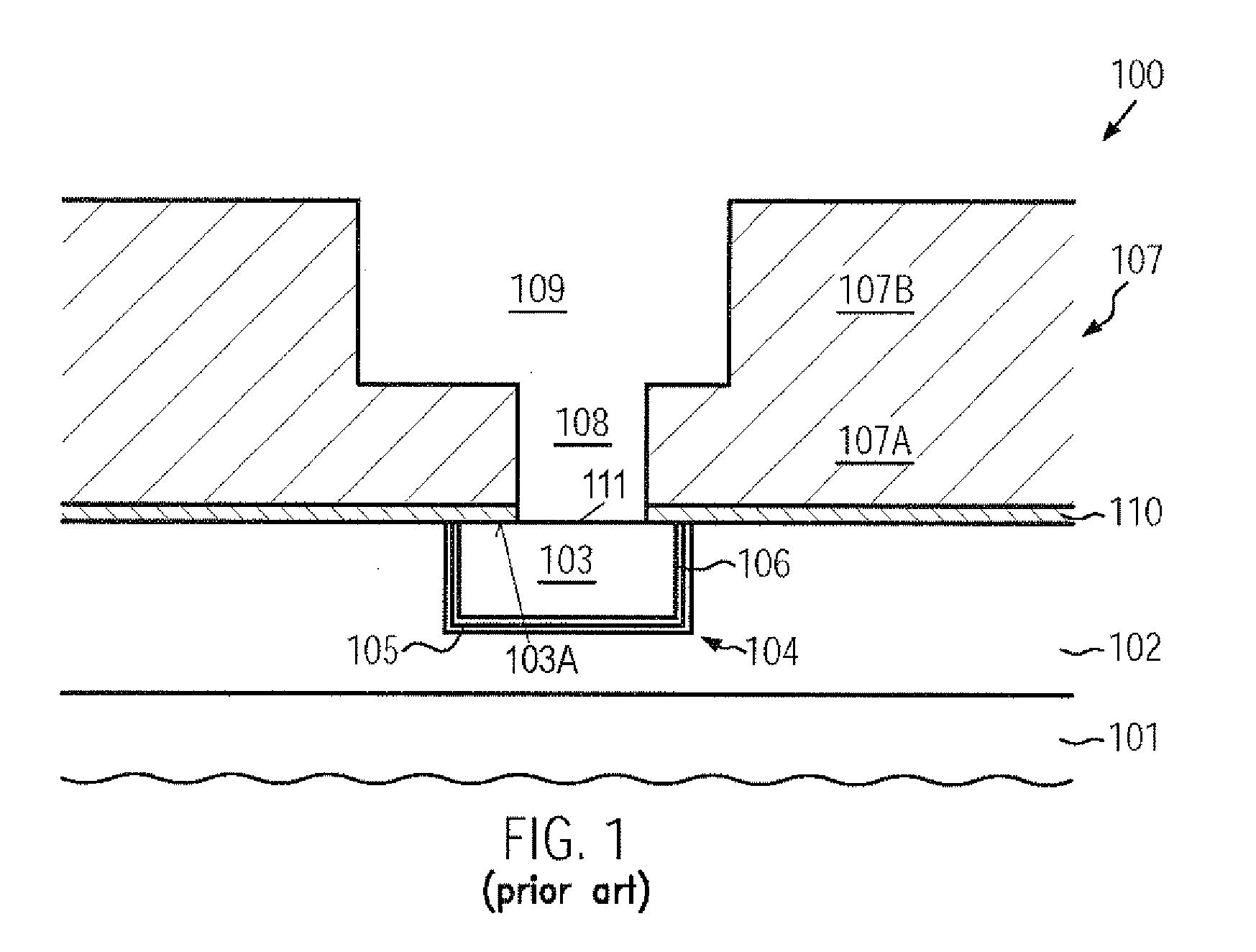
Moreover, any etch byproducts created during the preceding etch process for patterning the dielectric material may also have a negative impact on the exposed copper of the underlying metal region, as will be described with reference to FIG. 1 for a typical process technique for forming sophisticated copper-based integrated circuits.
Moreover, in sophisticated applications, the dielectric layer 107 may comprise sensitive dielectric materials having a dielectric constant of 2.7 and less, which may frequently be referred to as ultra low-k (ULK) dielectrics, which may also be affected by a wet chemical process, thereby resulting in any process non-uniformities during the further processing, for instance by depositing a conductive barrier material and a seed layer, depending on the corresponding process strategy.
Thus, in many cases, even under-etched areas may be created at lower sidewall portions of the via opening 108, which may result in a significant contact deterioration and which may require sophisticated process techniques, such as wet chemical etch processes on the basis of sophisticated chemistries and / or corresponding techniques for refilling any under-etched areas by an additional deposition process.
On the other hand, the exposed copper-containing surface of the metal region 104 may be exposed due to reactive components that may be present in the ambient atmosphere, even after performing the corresponding wet chemical etch process, thereby requiring further cleaning steps, for instance, prior to forming a conductive barrier layer and the like wherein, however, the more or less aggressive chemicals used during the preceding cleaning process may result in a certain degree of surface modification, thereby contributing to further process non-uniformities which may finally result in reduced contact reliability or production yield.

Method used


Image

  • Method for passivating exposed copper surfaces in a metallization layer of a semiconductor device
  • Method for passivating exposed copper surfaces in a metallization layer of a semiconductor device
  • Method for passivating exposed copper surfaces in a metallization layer of a semiconductor device

Examples


Embodiment Construction

[0024]Various illustrative embodiments of the invention are described below. In the interest of clarity, not all features of an actual implementation are described in this specification. It will of course be appreciated that in the development of any such actual embodiment, numerous implementation-specific decisions must be made to achieve the developers' specific goals, such as compliance with system-related and business-related constraints, which will vary from one implementation to another. Moreover, it will be appreciated that such a development effort might be complex and time-consuming, but would nevertheless be a routine undertaking for those of ordinary skill in the art having the benefit of this disclosure.

[0025]The present subject matter will now be described with reference to the attached figures. Various structures, systems and devices are schematically depicted in the drawings for purposes of explanation only and so as to not obscure the present disclosure with details ...


PUM

PropertyMeasurementUnit
temperatureaaaaaaaaaa
dielectric constantaaaaaaaaaa
time periodaaaaaaaaaa

Abstract

When forming sophisticated metallization systems, surface integrity of an exposed metal surface, such as a copper-containing surface, may be enhanced by exposing the surface to a vapor of a passivation agent. Due to the corresponding interaction with the metal surface, enhanced integrity may be accomplished, while at the same time damage of exposed dielectric surface portions may be significantly reduced compared to conventional aggressive wet chemical cleaning processes that are typically used in conventional patterning regimes.

Description

BACKGROUND OF THE INVENTION[0001]1. Field of the Invention[0002]Generally, the present disclosure relates to integrated circuits, and, more particularly, to the formation of metallization layers including highly conductive metals, such as copper, embedded into a dielectric material having low permittivity to enhance device performance.[0003]2. Description of the Related Art[0004]In an integrated circuit, a very large number of circuit elements, such as transistors, capacitors, resistors and the like, are formed in or on an appropriate substrate, usually in a substantially planar configuration. Due to the large number of circuit elements and the required complex layout of the integrated circuits, generally, the electrical connection of the individual circuit elements may not be established within the same level on which the circuit elements are manufactured, but requires one or more additional “wiring” layers, also referred to as metallization layers. These metallization layers gener...

Claims


Application Information

Patent Timeline
Patent Type & Authority Applications(United States)
IPC IPC(8): H01L21/768
CPCH01L21/321H01L21/76849H01L21/7684H01L21/76814
Inventor SCHALLER, MATTHIASFISCHER, DANIELLEPPACK, SUSANNE
Owner ADVANCED MICRO DEVICES INC
Why Eureka
Try Eureka