High pressure fuel pump control apparatus for internal combustion engine

a technology of internal combustion engine and control apparatus, which is applied in the direction of electrical control, process and machine control, instruments, etc., can solve the problems of unstable fuel pressure in the common rail, inability to achieve desired fuel quantity discharge control, and limitation of signal mode of camshaft sensor and cam nose number, so as to improve emission gas performance, stabilize the fuel system, and improve the effect of emission gas performan

Active Publication Date: 2010-04-01
HITACHI ASTEMO LTD
View PDF9 Cites 25 Cited by
  • Summary
  • Abstract
  • Description
  • Claims
  • Application Information

AI Technical Summary

Benefits of technology

[0016]The high pressure fuel pump control system for an internal combustion engine of the present invention configured as described above can calculate a suitable power distribution start or end demand phase in a drive timing calculating part in the control system to carry out the power distribution start and end in accordance with the demand phase in a drive signal output part in the control system, even when a camshaft phase varies by the variable valve timing control system for an internal combustion engine, and therefore can contribute to stabilization of a fuel system, stabilization of combustion, and improvement in emission gas performance.
[0017]Further, since desired discharge control of the high pressure fuel pump becomes enabled also when abnormality occurs in the crankshaft signal, the control system can contribute to stability of combustion and improvement in emission gas performance.
[0018]As will be understood from the above description, the high pressure fuel pump control system according to the present invention calculates a suitable power distribution start / end demand phase in a phase calculating part in the control system to make it possible to carry out start and end of power distribution in accordance with the above described demand phase in the drive signal output part in the above described control system. Therefore, the high pressure fuel pump control system can contribute to stabilization of a fuel system, stabilization of combustion, and improvement in emission gas performance.
[0019]Further, even when abnormality occurs in a position sensor signal, equivalent performance can be achieved.

Problems solved by technology

However, when the apparatus of the above described JP-A-2005-76554 is applied to an internal combustion engine having a variable valve timing control system, there is the problem of giving limitation to the signal mode of the camshaft sensor and the cam nose number for the pump of the camshaft which vertically moves in the cylinder in the high pressure pump.
More specifically, in the apparatus of the above described publication, the fuel discharge quantity control from the high pressure fuel pump is performed stably by controlling the ON / OFF timing of the solenoid valve with the camshaft sensor signal as an origin even when the phase of the camshaft linked with the high pressure fuel pump changes by the variable valve timing control system, however, this is limited to the case where the relative relationship of the camshaft sensor signal and the cam nose for driving the high pressure pump is consistent with each other.
When the number of drive cam noses of the camshaft which drives the high pressure fuel pump applied to this internal combustion engine is three, the timing for controlling ON / OFF of the solenoid valve from the camshaft sensor signal differs, and thus there is the problem that desired fuel quantity discharge control cannot be realized and the fuel pressure in the common rail becomes unstable.

Method used


Image

  • High pressure fuel pump control apparatus for internal combustion engine
  • High pressure fuel pump control apparatus for internal combustion engine
  • High pressure fuel pump control apparatus for internal combustion engine

Examples


Embodiment Construction

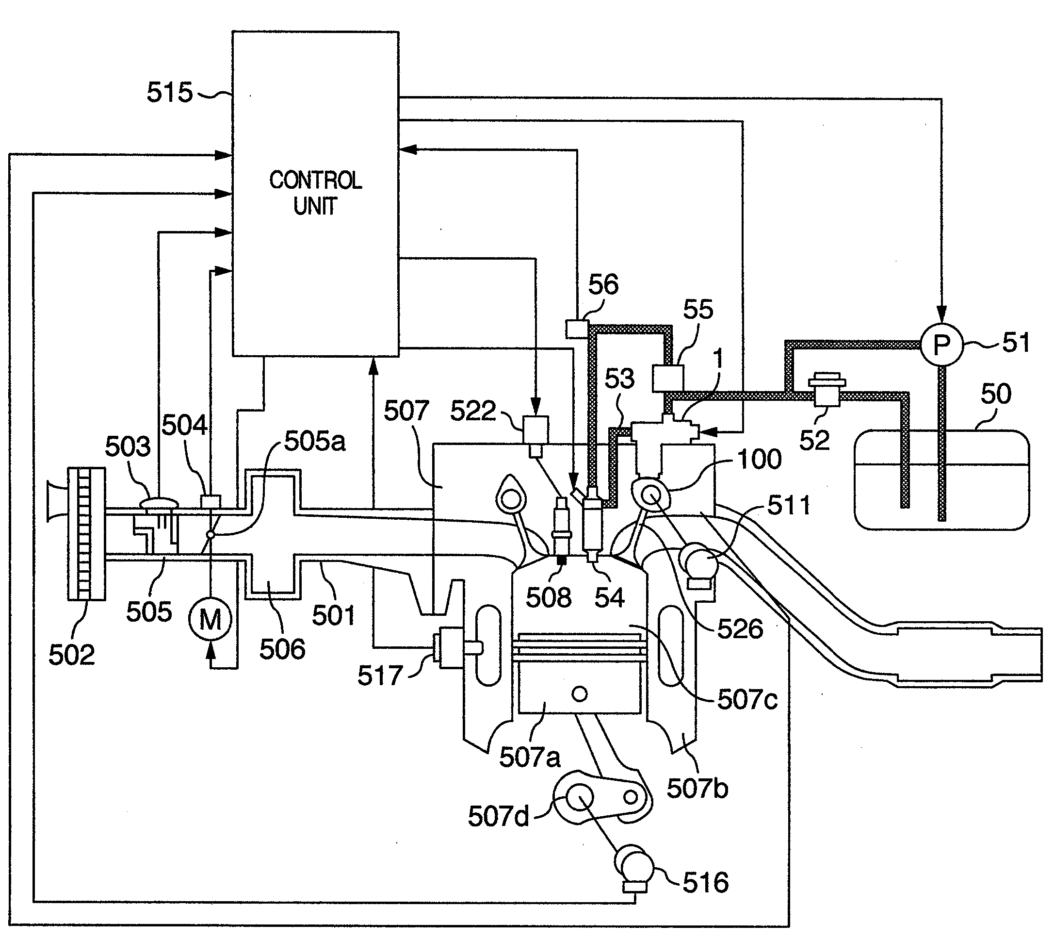
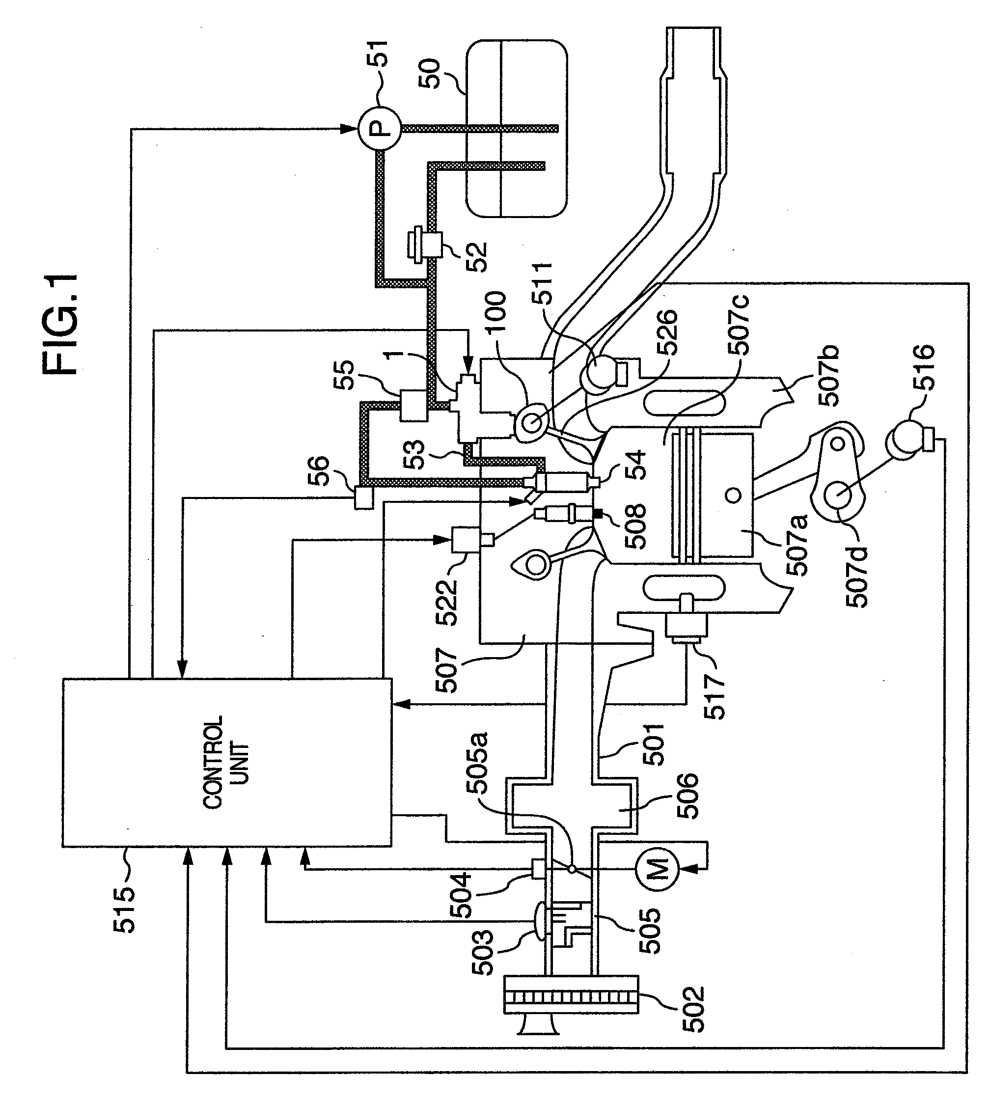
[0038]Hereinafter, one embodiment of a high pressure fuel supply control system in an internal combustion engine of the present invention will be described based on the drawings. FIG. 1 shows an entire configuration of a control system of a direct injection engine 507 of the present embodiment. The direct injection engine 507 includes four cylinders. Air, which is introduced into each cylinder 507b, is taken in from an inlet part of an air cleaner 502, passes through an air flow meter (air flow sensor) 503 and through a throttle body 505 housing an electrically controlled throttle valve 505a which controls an intake flow rate, and enters a collector 506. The air which is sucked into the above described collector 506 is distributed to each intake pipe 501 connected to each cylinder 507b of the engine 507, and thereafter, the air is guided to a combustion chamber 507c which is formed by a piston 507a, the above described cylinder 507b and the like. From the above described air flow se...


PUM


Abstract

There is provided a high pressure fuel pump control system for an internal combustion engine which enables fuel pressure control with high precision without being restricted by the number of cylinders of the internal combustion engine or the number of phase sensor signals and the number of cam noses which vertically drives a plunger of a high pressure fuel pump even when a camshaft phase varies by a variable valve timing mechanism by using the high pressure fuel pump with a solenoid valve. The control system has a means which changes an effective stroke by driving the solenoid valve in the high pressure fuel pump, and has a means which changes the drive timing of the high pressure fuel pump based on a cylinder recognition value of the internal combustion engine with the cam angle detecting means as an origin.

Description

BACKGROUND OF THE INVENTION[0001]1. Field of the Invention[0002]The present invention relates to an apparatus for an internal combustion engine mounted on an automobile or the like, and particularly to a high pressure fuel supply apparatus including a high pressure fuel pump.[0003]2. Description of the Related Art[0004]Present automobiles are required to reduce emission gas substances such as carbon monoxide (CO), hydrocarbon (HC) and nitrogen oxide (NOx), which are included in emission gas of the automobiles, from the viewpoint of environmental conservation, and for the purpose of reduction of the emission gas substances, development of a direct injection engine has been carried out. In the above described direct injection engine, a fuel within a common rail of which pressure is regulated into a high fuel pressure by a high pressure fuel pump is directly injected into a combustion chamber of a cylinder by an injector, to attempt reduction or the like of the emission gas substances ...

Claims


Application Information

Patent Timeline
Patent Type & Authority Applications(United States)
IPC IPC(8): F02D41/00F02M57/02
CPCF02D41/009F02D41/222F02M59/367F02M59/366F02D41/3845
Inventor TOYOHARA, MASAHIROKONDO, KAZUNORIOKUBO, SATORUOKAMOTO, TAKASHI
Owner HITACHI ASTEMO LTD
Why Eureka
Try Eureka