Process for producing fiber and method for producing catalyst layer
a technology of catalyst layer and fiber, which is applied in the field of process for producing fiber and a method for producing catalyst layer, can solve the problems of low gas diffusion in the catalyst layer, inability to achieve the membrane/electrode assembly obtainable by such a method, and inability to achieve the gas diffusion property of the catalyst layer formed by the method (1) or (2), etc., to achieve the effect of easy production of ultrafine fibers, low cost and easy production of catalyst layers with high gas diffusion properties
- Summary
- Abstract
- Description
- Claims
- Application Information
AI Technical Summary
Benefits of technology
Problems solved by technology
Method used
Image
Examples
example 1
Preparation of Polymer Electrolyte Membrane:
[0201]On an ethylene / tetrafluoroethylene copolymer (hereinafter referred to as ETFE) film (manufactured by Asahi Glass Company, Limited, thickness: 100 μm), a water / ethanol solution (solvent composition: water / ethanol=4 / 6 by mass ratio, solid content: 27 mass %) of a polymer (H11) (manufactured by Asahi Glass Company, Limited, Flemion R, ion exchange capacity: 1.1 meq / g dry resin) having repeating units based on TFE and repeating units represented by the following formula (11), was cast and dried at 80° C. for 30 minutes in a commercially available circulation type dryer, to obtain a polymer electrolyte membrane having a thickness of 10 μm. Further, the same operation was repeated twice to obtain polymer electrolyte membrane (MA1) having a thickness of 30 μm provided with the ETFE film. Further, it was heated at 160° C. for 30 minutes in the commercially available circulation type dryer to carry out annealing treatment.
Preparation of Spinn...
example 2
Formation of Catalyst Layer (C2):
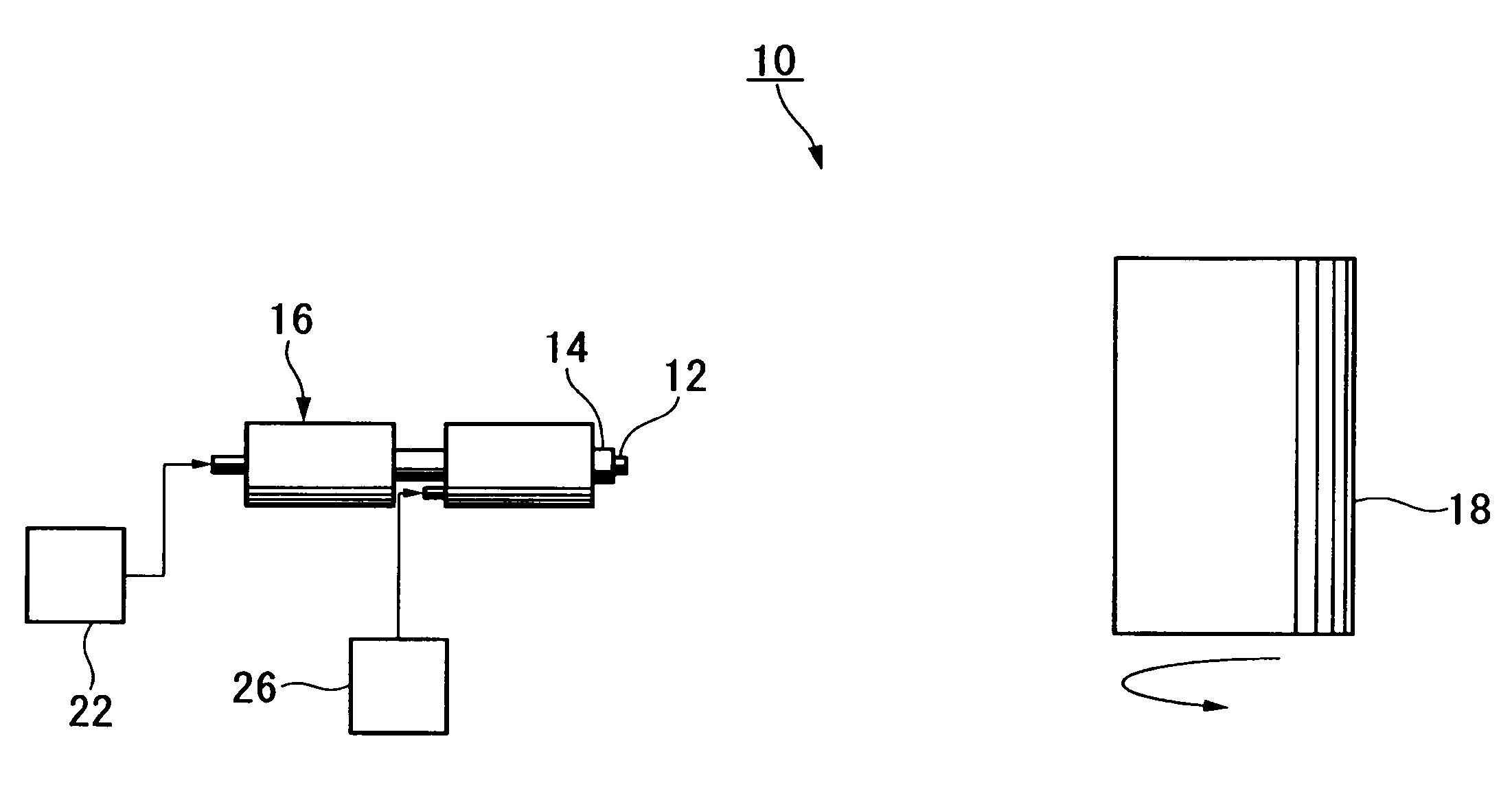
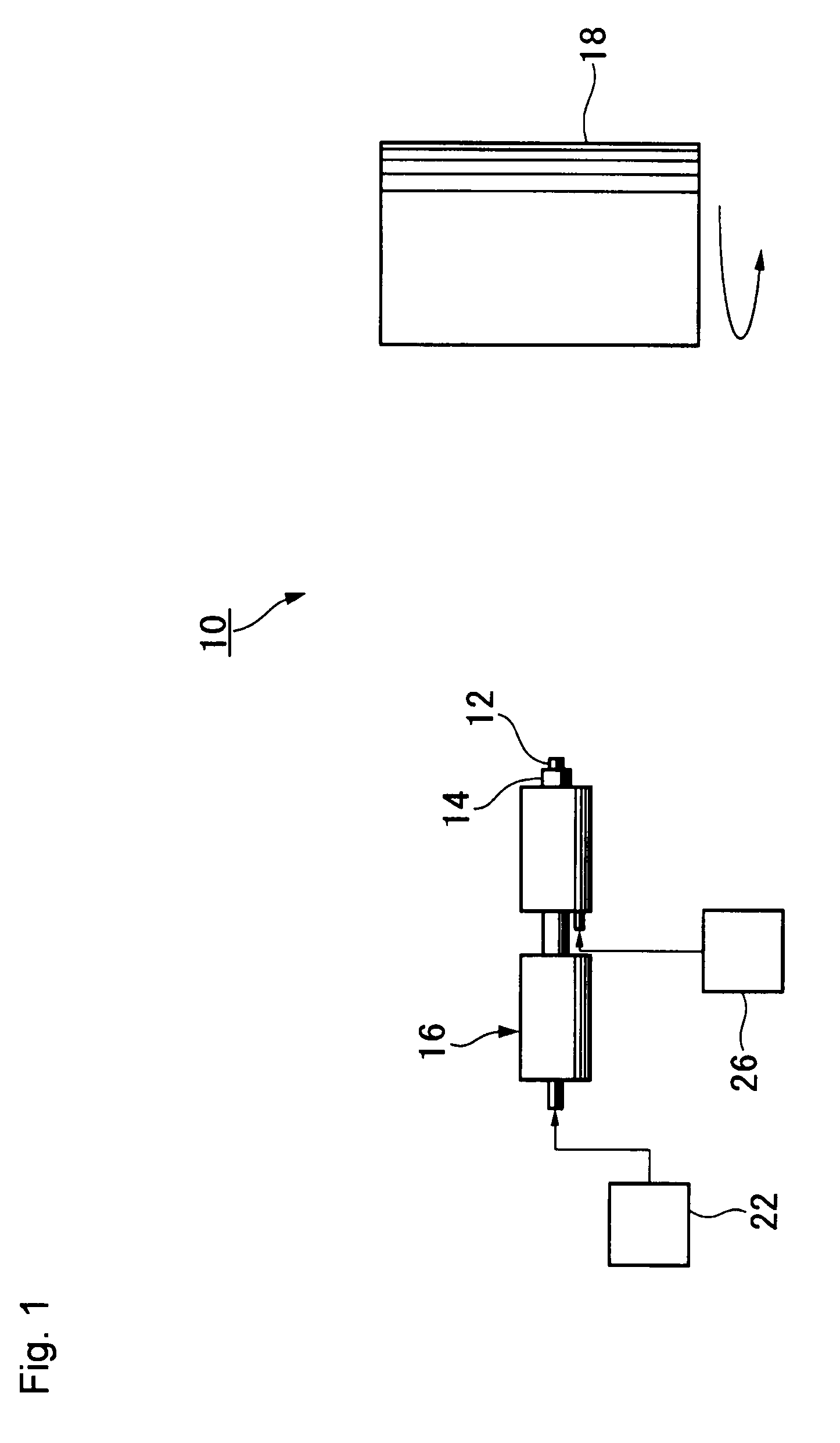
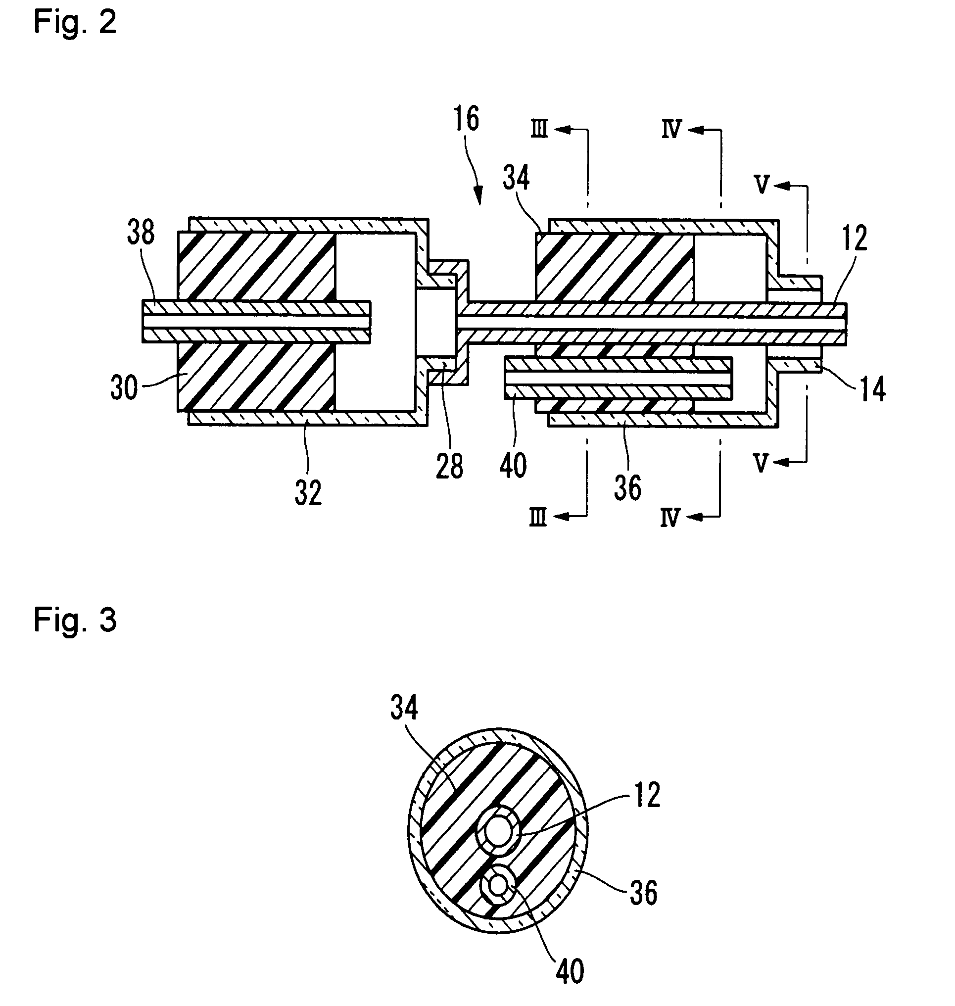
[0214]In the same manner as in Example 1 except that the discharge amount of the spinning solution (b1) from the outside nozzle 42 was changed to 3 mL / hr, a core-in-sheath fiber (β) as illustrated in FIG. 12 was formed, and such a fiber was accumulated on the polymer electrolyte membrane (MA1) to form a non-woven fabric, thereby to form a catalyst layer (C2) on the cathode side, whereby a membrane / catalyst layer assembly (MC2) was obtained.
[0215]The average fiber diameter of the fiber constituting the non-woven fabric and the deposition efficiency of the catalyst are shown in Table 1. No fiber having a fiber length of at most 3 mm was observed. The bulk density of the catalyst layer (C2) was 0.8 g / cc, and the amount of platinum per unit area was 0.30 mg / cm2.
[0216]Further, with respect to the membrane / catalyst layer assembly (MC2), the gas diffusion property, electrical conductivity and water resistance were evaluated. The results are shown in Table 2...
example 3
Formation of Catalyst Layer (C3):
[0219]In the same manner as in Example 1 except that the discharge amount of the spinning solution (c1) from the inside nozzle 42 was changed to 2 mL / hr, a core-in-sheath fiber (β) as illustrated in FIG. 12 was formed, and such a fiber was accumulated on the polymer electrolyte membrane (MA1) to form a non-woven fabric thereby to form a catalyst layer (C3) on a cathode side, whereby a membrane / catalyst layer assembly (MC3) was obtained.
[0220]The average fiber diameter of the fiber constituting the non-woven fabric and the deposition efficiency of the catalyst are shown in Table 1. No fiber having a fiber length of at most 3 mm was observed. The bulk density of the catalyst layer (C3) was 0.8 g / cc, and the amount of platinum per unit area was 0.34 mg / cm2.
[0221]Further, with respect to the membrane / catalyst layer assembly (MC3), the gas diffusion property, electrical conductivity and water resistance were evaluated. The results are shown in Table 2.
Pre...
PUM
| Property | Measurement | Unit |
|---|---|---|
| particle size | aaaaa | aaaaa |
| electrically conductive | aaaaa | aaaaa |
| energy efficiency | aaaaa | aaaaa |
Abstract
Description
Claims
Application Information
 - R&D
- Intellectual Property
- Life Sciences
- Materials
- Tech Scout
- Unparalleled Data Quality
- Higher Quality Content
- 60% Fewer Hallucinations
Browse by: Latest US Patents, China's latest patents, Technical Efficacy Thesaurus, Application Domain, Technology Topic, Popular Technical Reports.
© 2025 PatSnap. All rights reserved.Legal|Privacy policy|Modern Slavery Act Transparency Statement|Sitemap|About US| Contact US: help@patsnap.com


