System and Methods for Improving Efficiency in Internal Combustion Engines

a technology of internal combustion engine and control system, which is applied in the direction of electrical control, process and machine control, instruments, etc., can solve the problems of increasing the cost of operation, reducing the efficiency of current internal combustion engine, and releasing large amounts of undesirable emissions, so as to improve the efficiency of internal combustion engine and maximize the percentage of time

Active Publication Date: 2010-04-22
TULA TECH INC
View PDF83 Cites 120 Cited by
  • Summary
  • Abstract
  • Description
  • Claims
  • Application Information

AI Technical Summary

Benefits of technology

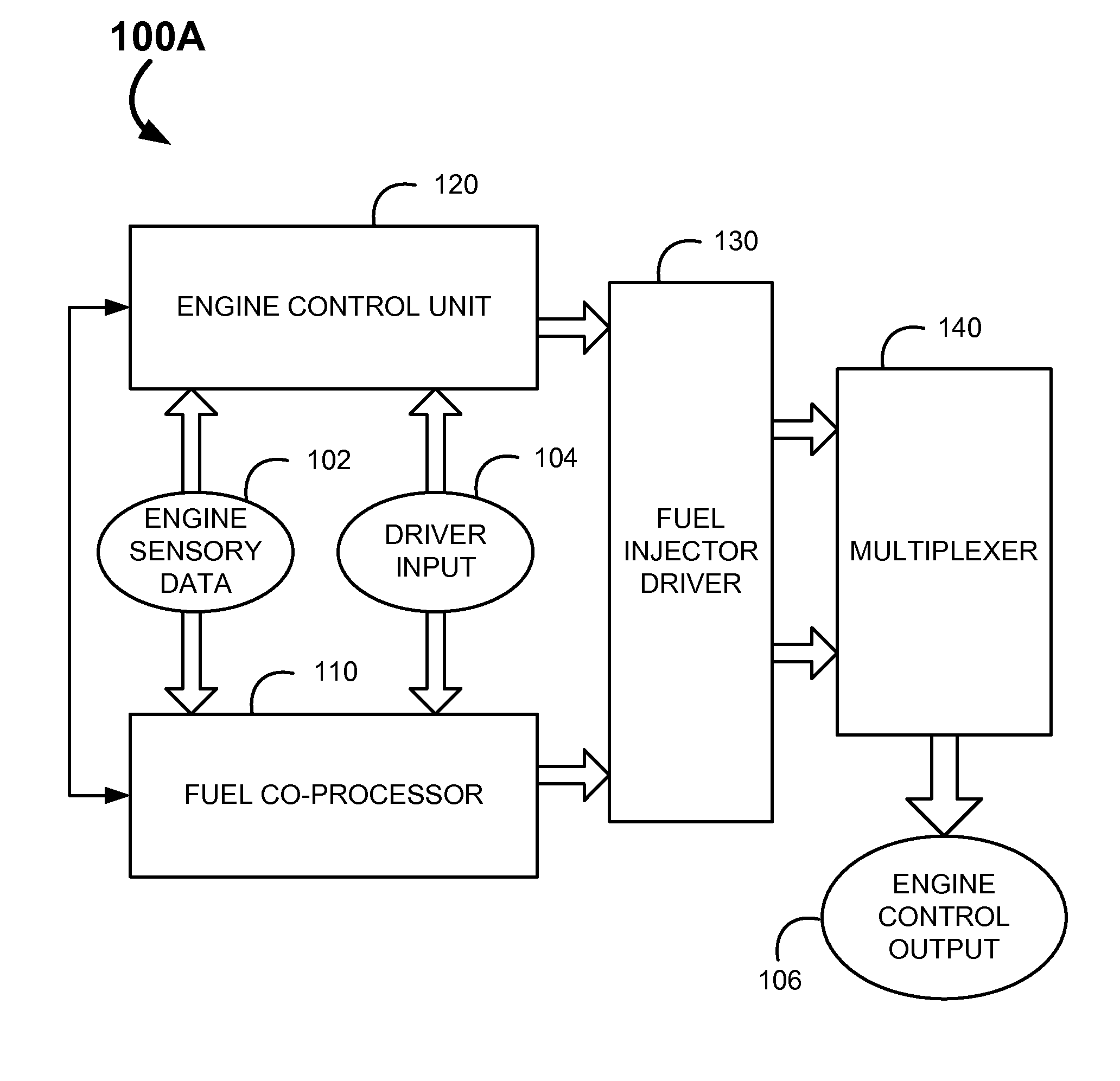
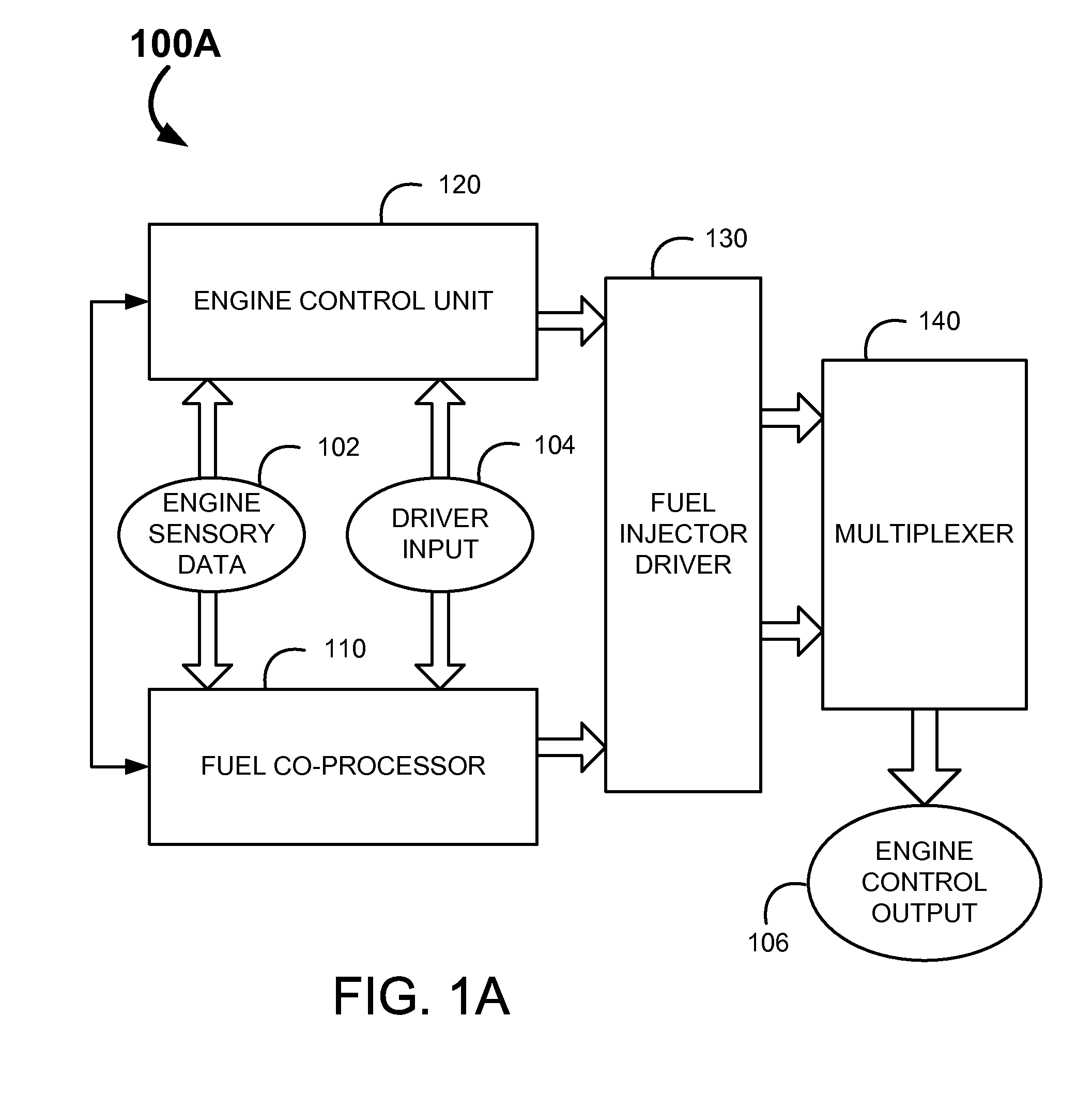
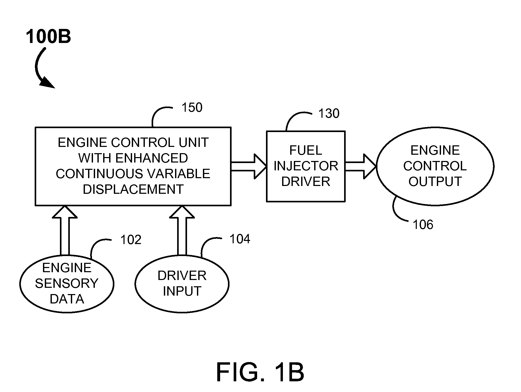
[0025]The present invention discloses an engine control system. More particularly, the present invention teaches systems and methods for improving efficiency in internal combustion engines. The engine control system may be utilized to modify current engines to operate in advanced variable displacement modes where cylinders are activated in order to maximize the percentage of time that each working chamber operates at optimal efficiency.
[0031]Then the system substantially disables fuel flow to and air flow to the deactivated cylinders by shutting the intake and exhaust valves of the deactivated cylinders. The system also substantially disables fuel flow to and firing of the passive cylinders. However, unlike the deactivated cylinders, air passes through the passive cylinders. Moreover, the system substantially regulates fuel flow to, air flow to and firing of the working cylinders. Thus, the working cylinders act as normal firing cylinders. Firing of the working cylinders may be synchronized with engine speed to reduce unwanted engine vibrations and ensure smooth engine operation.

Problems solved by technology

Current internal combustion engines are notoriously inefficient.
Such inefficiency results in smaller distances required between fill ups, increased costs of operation and the release of greater amounts of undesirable emissions, including greenhouse gasses, as compared to more efficient engine types.
However, there is often a tradeoff of fuel saving features to performance.
Also, in regards to some of the more extreme fuel saving features, such as hybrid systems, conversion of existing internal combustion engine vehicles is difficult and often financially prohibitive.
Moreover, few of the current measures utilized to increase engine efficiency actually address the root cause of the inefficiencies.
However, in engines that control the power output by using a throttle to regulate the flow of air into the cylinders (e.g., Otto cycle engines used in many cars), operating at an un-throttled position (i.e., at “full throttle”) would typically result in the delivery of more power (and often far more power) than desired or appropriate.
Operating such engines at thermodynamically optimal fuel injection levels, again, would typically result in the delivery of more power than desired or appropriate.
Therefore, in most applications, standard internal combustion engines are operated under conditions well below their optimal thermodynamic efficiency a significant majority of the time.
There are a number of reasons that internal combustion engines do not operate as efficiently at partial throttle.
One of the most significant factors is that less air is provided to the cylinder at partial throttle than at full throttle which reduces the effective compression of the cylinder, which in turn reduces the thermodynamic efficiency of the cylinder.
Another very significant factor is that operating at partial throttle requires more energy to be expended to pump air into and out of the cylinders than is required when the cylinder is operating at full throttle—these losses are frequently referred to as pumping losses.
The luxury sedan's engine flipped between four, six and eight cylinders, but had a poor service record and suffered from engine vibration issues.
The greatest vibration problems kicked in when the engine was in six-cylinder mode, an intrinsically unbalanced configuration.
The technology was deemed too unstable, with too little demand to be developed until recently.
When a cylinder is “shut down”, its piston still reciprocates, however neither air nor fuel is delivered to the cylinder so the piston does not deliver any power during its power stroke.
Although the remaining cylinders tend to operate at improved efficiency, they still do not operate at their optimal efficiency the vast majority of the time because they are still not operating consistently at “full throttle.” That is, they have the same drawbacks of partial throttle operations, (e.g., lower compression, higher pumping losses) even though the scale of their inefficiencies is reduced.
Another drawback of most current commercially available variable displacement engines is that they tend to revert out of the variable displacement mode very quickly when changes are made to the desired operational state of the engine.
It is believed that the reason that such variable displacement engines kick out of the variable displacement mode so quickly is due to the perceived difficulty of controlling the engine to provide substantially the same response regardless of how many cylinders are being used at any given time.
Although such designs may improve thermodynamic and fuel efficiencies, existing variable cylinder size designs tend to be relatively complicated and expensive to produce making them impractical for widespread use in commercial vehicles.
Furthermore, in many existing engines used by current vehicles, the number of cylinders capable of being “shut down” when in variable displacement modes may be limited.
In virtually all such engines, current methods of variable displacement modes are unable to provide low power one or two cylinder operation.
Thus, the time spent in a reduced displacement mode is typically limited, resulting in reduced efficiency realization.
Again, this results in the engine being run at a lower than peak efficiency rating.
Additionally, variable displacement modes may result in strains being placed upon the exhaust systems of the engines.
This may result in the engines failing compliance to state and federal emissions standards.
When a 3-way catalyst is used in an open-loop system, NOx reduction (one of the three reactions) efficiency is low.
However, outside of that band, conversion efficiency falls off very rapidly.
When there is excessive fuel, then the engine is running rich.
If both sensors give the same output, the catalytic converter is not functioning and must be replaced.
During variable displacement operation, readings by the oxygen sensors may be erratic and may signify “improper” engine operation.
Regardless, being in compliance with emissions standards is imperative for most automotive engines, and has resulted in hurdles to the development of successful wide range variable displacement systems.

Method used


Image

  • System and Methods for Improving Efficiency in Internal Combustion Engines
  • System and Methods for Improving Efficiency in Internal Combustion Engines
  • System and Methods for Improving Efficiency in Internal Combustion Engines

Examples


example two

III. Example Two

Six Chamber Dual Exhaust Engines

[0237]FIGS. 14A to 18E are functional permutations of an example V6 style internal combustion engine in conventional operation. This style engine is functionally similar to the Honda™ V6 J-series engine. Of course, many V6 style engines are functionally similar to the exemplary diagram.

[0238]The six cylinder Honda™ engine is capable of shutting down 2 or 3 cylinders. The system uses the i-VTEC system to turn off one bank of cylinders under light loads, turning the V6 into a straight-3. The latest Variable Cylinder Management system is able to turn off one bank of cylinders or one cylinder on opposing banks, allowing for three-cylinder use under light loads and four-cylinder use under medium loads.

[0239]The Honda J series engine deactivates specific cylinders by using the VTEC (Variable Valve-Timing and Lift Electronic Control) system to close the intake and exhaust valves while simultaneously the Powertrain Control Module cuts fuel to ...

example three

IV. Example Three

Five Chamber Engines

[0327]In addition to the present invention being of use with V type engines, there is considerable opportunity for a variable displacement system, as discussed in this application, to be utilized in conjunction with standard in line style engines. For the following examples, a 5-cylinder inline engine will be discussed.

[0328]The 5-cylinder engine's advantage over a comparable 4-cylinder engine is best understood by considering power strokes and their frequency. A 4-cycle engine fires all its cylinders every 720 degrees, the crankshaft makes two complete rotations. If an even firing engine is assumed, 720 degrees may be divided by the number of cylinders to determine how often a power stroke occurs. In regards to a four cylinder engine: 720 degrees÷4=180 degrees, so a 4-cylinder engine gets a power stroke every 180 degrees. Thus, a V8 engine gets a power stroke every 90 degrees, (720°÷8=90°).

[0329]A given power stroke may last no more than 180 deg...


PUM


Abstract

The present invention relates to system and methods for improving efficiency of an internal combustion engine. This system may include a fuel processor. The system receives instructions for a desired engine output and operating conditions. The system may then determine an operational state corresponding to the desired output. The operational state includes designating the cylinders into one of three categories: working, deactivated and passive. The number of working cylinders is calculated by dividing the desired output by the power provided by one cylinder operating at substantially optimal efficiency. Then the system substantially disables fuel flow to and air flow to the deactivated cylinders, substantially disables fuel flow to and firing of the passive cylinders, and substantially regulates fuel flow to, air flow to and firing of the working cylinders. Firing of the working cylinders is synchronized with engine speed to reduce unwanted engine vibrations. The number of working, passive and deactivated cylinders may be continually altered in response to changes in desired output or operating conditions.

Description

RELATED APPLICATIONS[0001]This application claims the priority of U.S. Provisional Patent Application No. 61 / 080,192, filed Jul. 11, 2008; U.S. Provisional Patent Application No. 61 / 104,222, filed Oct. 9, 2008; and U.S. Provisional Patent Application No. 61 / 224,817, filed Jul. 10, 2009. All of these priority applications are incorporated herein by reference and are entitled: “Internal Combustion Engine Control for Improved Fuel Efficiency.”[0002]This application is also a continuation-in-part of U.S. patent application Ser. No. 12 / 501,345 filed on Jul. 10, 2009, entitled “Internal Combustion Engine Control for Improved Fuel Efficiency”, which is a continuation-in-part of U.S. patent application Ser. No. 12 / 355,725 filed on Jan. 16, 2009, entitled the same. The content of these applications are incorporated herein by reference.BACKGROUND OF THE INVENTION[0003]The present invention relates to internal combustion engine control systems and methods. More particularly, the present invent...

Claims


Application Information

Patent Timeline
Patent Type & Authority Applications(United States)
IPC IPC(8): F02D43/00
CPCF02D37/02F02D41/0087F02D41/1401F02D41/266Y02T10/46F02D2250/18F02D2400/02F02P5/1512F02D2200/602Y02T10/40
Inventor TRIPATHI, ADYA S.SILVESTRI, CHESTER J.
Owner TULA TECH INC
Why Eureka
Try Eureka