Self-regulating electrical resistance heating element

Inactive Publication Date: 2010-04-29
2D HEAT LTD
View PDF5 Cites 10 Cited by
  • Summary
  • Abstract
  • Description
  • Claims
  • Application Information

AI Technical Summary

Benefits of technology

[0046]The resistive properties of the doped barium titanates derive mainly from the grain boundary effects at the junctions between successive particles; The smaller the particle size range, the greater the number in any given volume of the barium titanate layer, and the greater th

Problems solved by technology

Conventional electrical heating elements of the tubular sheathed variety or screen printed type do not have self-regulating properties and when connected to an electrical power source will continue to heat up until they fail by burning out and self-destructing.
Generally these temperature sensitive control devices incorporate bimetals in various configurations and rely on the ability of the bimetallic components to deflect at or around a predetermined temperature to provide a mechanical action which “breaks” the electrical supply contacts, thus interrupting the electrical power supply to the elements concerned.
Whilst such temperature sensitive bimetallic and other similar control devices are widely used, and are produced to high quality standards, they are generally mechanical and like all mechanical mass produced devices are subject to the probability of failure, which increases with usage.
The operational failure of such temperature sensitive control devices will result in the over-heating and self-destruction of the associated elements, with potentially catastrophic results for the user.
However, such heating elements have a number of limitations which severely limit their widespread application and usage.
Some of these are set out below:The major disadvantage of doped barium titanates is the inherent property that the resistivity of such materials is not constant over the temperature range from ambient to the “switching” temperature or Curie Point, but rather resistivity reduces progressively with increasing temperature before increasing to a high value.A further disadvantage is that the rate and magnitude of reduction of resistance in such materials varies appreciably according to the composition and concentration(s) of the dopant or combination of do

Method used


Image

  • Self-regulating electrical resistance heating element
  • Self-regulating electrical resistance heating element
  • Self-regulating electrical resistance heating element

Examples


Example

Example 1

Construction

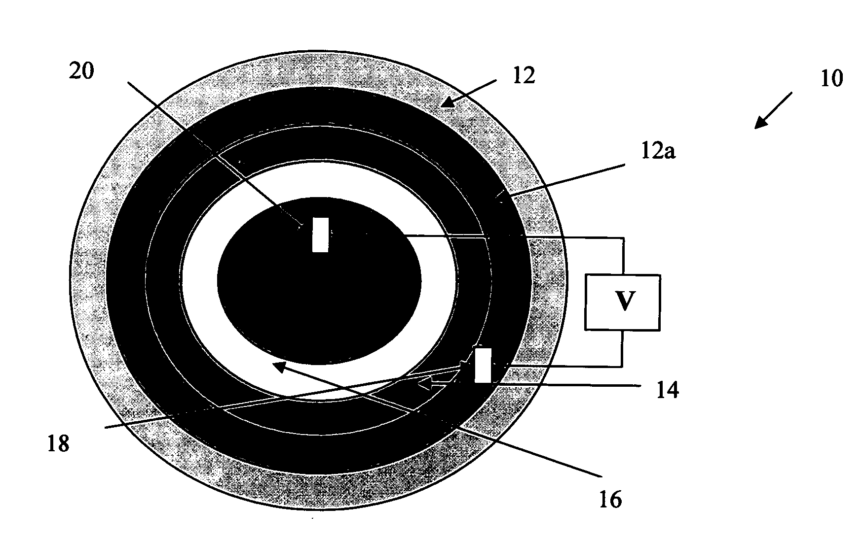
[0061]Referring to FIG. 3 the self regulating electrical resistance heating element (10) comprises a substrate (12) comprising an electrically conductive coating (12a) which serves as a first electrical contact (18) on one side of the composite metal oxide layers. Disposed on said electrically conductive layer (12a) is a first metal oxide (14) which has a positive temperature coefficient of resistance. Overlaying the first metal oxide layer, and in electrical series thereto, is a second metal oxide layer (16) having a negative temperature coefficient of resistance and overlaying this layer is a second electrical contact (20).

[0062]The first and second metal oxide layers are in intimate contact with each other, but in an alternative example an electrically contacting layer (not shown) can be provided there between.

[0063]A current can be passed between the first and second electrical contacts, through the respective metal oxide layers.

[0064]In the embodiment illus...

Example

Example 2

Methodology

[0074]The heating elements may be manufactured by, for example, thermally spraying a resistive metal oxide (14) with a positive temperature coefficient of resistance onto an electrically conductive surface (12a) of a substrate (12). Indeed, successive layers of the metal oxide may be applied by making a plurality of passes (anywhere from 1 to 10, more preferably 2 to 5, depending on the desired thickness—typically up to 500 μm) using thermal spray equipment. Since the electrical resistance of the resistive metal oxide deposit is dependent upon the thickness, it is possible to increase the resistance by increasing the thickness of the layer deposited. It is therefore preferred to deposit several layers.

[0075]It is known that metal alloys comprised of the nickel-chrome type when oxidised and thermally sprayed exhibit the desired characteristic of increasing resistivity / resistance with increased temperature. Such metal alloys are described in, for example, EP302589,...

Example

Example 3

Alternative Methodology

[0088]The metal oxides comprising the different layers of the self-regulating heating element may be applied to the supporting substrate in a variety of ways using different techniques.

[0089]A first methodology is to deposit a first metal oxide produced from e.g. Ni—Cr—Fe or similar alloys as one complete layer over the conductive surface of a substrate. It may be deposited by thermally spraying it over a given area and in a given configuration to the required calculated thickness. The second metal oxide, produced from e.g. doped barium titinate is then applied over the first metal oxide, again to the required calculated thickness and configuration the object being to “match” the two metal oxides to produce the required combined properties and characteristics of the heating element concerned.

[0090]Alternatively, the reverse of this first methodology may be utilised, whereby the oxygen-octahedral-ferro-electric oxide component is firstly applied to the...


PUM

PropertyMeasurementUnit
Thicknessaaaaaaaaaa
Particle sizeaaaaaaaaaa
Electrical conductivityaaaaaaaaaa

Abstract

The present invention relates to a self-regulating electrical resistance heating element, to an appliance containing same, and to processes for their manufacture. The self regulating electrical resistance heating element (10) comprises a substrate (12) comprising an electrically conductive coating (12a) which serves as a first electrical contact (18) on one side of the composite metal oxide layers. Disposed on said electrically conductive layer (12a) is a first metal oxide (14) which has a positive temperature coefficient of resistance. Overlaying the first metal oxide layer, and in electrical series thereto, is a second metal oxide layer (16) having a negative temperature coefficient of resistance and overlaying this layer is a second electrical contact (20). The second metal oxide layer (16) having a negative temperature coefficient of resistance is applied to the element in a manner which ensures it's resistive characteristics are not altered.

Description

TECHNICAL FIELD[0001]The present invention relates to a self-regulating electrical resistance heating element, to an appliance containing same, and to processes for their manufacture.BACKGROUND OF THE INVENTION[0002]Conventional electrical heating elements of the tubular sheathed variety or screen printed type do not have self-regulating properties and when connected to an electrical power source will continue to heat up until they fail by burning out and self-destructing.[0003]The safe use of these conventional elements in appliances is achieved by combining them in series with some form of temperature sensitive control device, which effectively cuts off the electrical supply when a predetermined temperature level has been reached.[0004]Generally these temperature sensitive control devices incorporate bimetals in various configurations and rely on the ability of the bimetallic components to deflect at or around a predetermined temperature to provide a mechanical action which “break...

Claims


Application Information

Patent Timeline
IPC IPC(8): H05B3/02H01C7/04
CPCH05B2203/019H05B2203/02H01C7/021H01C7/025Y10T29/49082H01C7/046H01C7/06H05B3/141H01C7/041H01C17/06533H01C7/02H01C7/04H05B3/14
Inventor BOARDMAN, JEFFERY
Owner 2D HEAT LTD
Why Eureka
Try Eureka