OLED with metal complexes having a high quantum efficiency

a metal complex and quantum efficiency technology, applied in the direction of discharge tube luminescent screen, discharge tube/lamp details, luminescent compositions, etc., can solve the problems of general limited performance and some drawbacks in the field of luminescent deterioration, and achieve good color purity, increase the efficiency of the light-emitting layer, and suitable solubility and thermal stability

Inactive Publication Date: 2010-05-06
KONINKLIJKE PHILIPS ELECTRONICS NV
View PDF5 Cites 6 Cited by
  • Summary
  • Abstract
  • Description
  • Claims
  • Application Information

AI Technical Summary

Benefits of technology

[0008]It is therefore an object of the present invention to provide a device which is able to at least partially overcome some of the above-mentioned drawbacks and helps to increase the efficiency of the light-emitting layer whilst showing good color purity and suitable solubility and thermal stability to be easily applied.
[0010]It has been shown for a wide range of applications within the present invention that by using such complexes the OLED will have an increased efficiency of the light emitting layer without deteriorating the further features of the OLED such as good colour purity and thermal stability—actually for a wide range of applications within the present invention, these other features can even be improved, too.
[0011]In a preferred embodiment of the present invention the OLED comprises a metal complex in the luminescent layer where the said one tailored ligand has a combined triplet energy of ≧16,000 cm−1. More preferred the ligand has a combined triplet energy between ≧16,000 cm−1 and ≦19,500 cm−1.In a preferred embodiment of the present invention the OLED comprises a metal complex in the luminescent layer where the complex has an improved quenching behavior.
[0037]Advantageously, the OLEDs of the present invention comprising a metal complex compound with at least one tailored ligand having a triplet energy of ≧16,000 cm−1 in the light-emitting layer show an improved photoluminescence efficiency because a higher concentration of the luminescent compound can be incorporated in the light-emitting layer. Quenching of the excited state is reduced by repressing dimer formation. This goal can be achieved on the ground of a greater distance of the metal complex molecules due to the increased size of the ligands. Moreover, the ligands in the metal compounds of the present invention are more rigid which also results in an increased photoluminescence efficiency. Furthermore, the luminescent compounds of the present OLEDs have a high triplet energy whilst having at the same time a high grade of conjugation. Thus, charge transfer can be improved without shift of the emitted wavelength to the non-visible spectra.

Problems solved by technology

While organic electroluminescent (EL) devices have been known for over two decades, their performance is generally limited due to several adverse effects.
However, the above mentioned organic light-emitting materials utilizing phosphorescence have been accompanied by some drawbacks in the field of luminescent deterioration.

Method used


Image

  • OLED with metal complexes having a high quantum efficiency
  • OLED with metal complexes having a high quantum efficiency
  • OLED with metal complexes having a high quantum efficiency

Examples


example 1

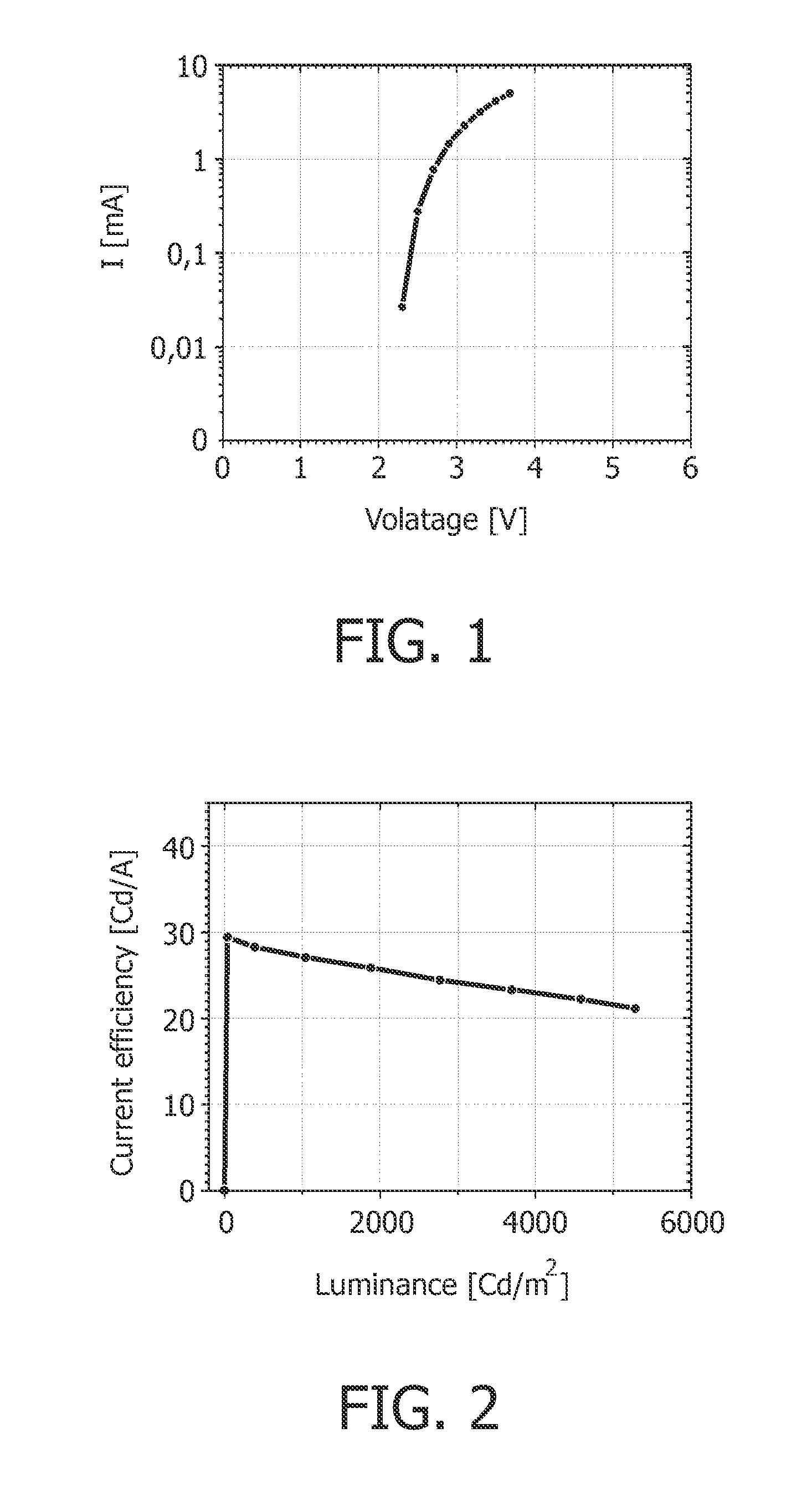
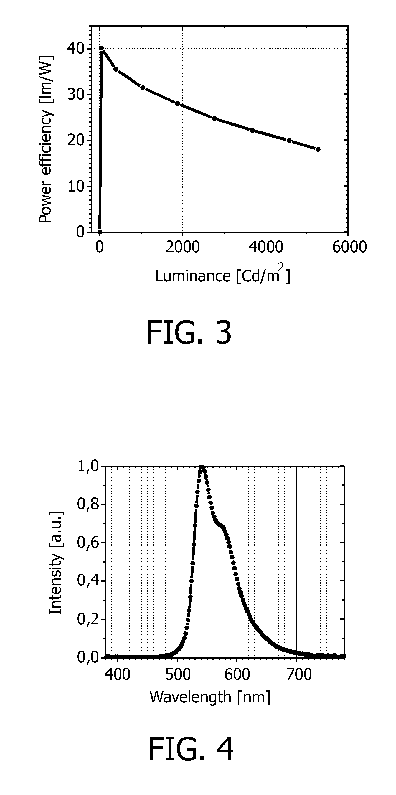
[0086]Emitter Ir(2t-ppy) is doped into a matrix consisting of n-MTDATA. The detailed structure of the OLED device is shown in the table below. The triplet energy of Ir(2t-ppy) is 18600 cm−1.

TABLE 1Layer structure OLED device according to example 1.LayerMaterialthicknessAnodeITO120nmHole injection layerNHT1:NDP220nmHole transport layern-MTDATA10nmMatrix:Emittern-MTDATA:Ir(2t-25nmppy) 8 at %Electron transport layerTPBI10nmElectron injection layerNET5:NDN145nmCathodeAl100 nmITO = Indium tin oxide.n-MTDATA = 4,4′,4″-Tris(N-(1-naphthyl)-N-phenyl-amino)-triphenylamineTPBI = 1,3,5-tris-(1-phenyl-1H-benzimidazol-2-yl)-benzeneNHT1, NDP2, NET5, NDN1 are products of Novaled GmbH Dresden.NHT1:NDP2 is used to enhance inject of holes, andNET5:NDN1 is used to enhance injection ofelectrons into the OLED device.Formula 4: Structure of the emitter used in example 1.

[0087]The OLED device according to example 1 has at 1000 Cd / m2 a current efficiency of 27.2 Cd / A, and a power efficiency is 32.1 μm / W.

example 2

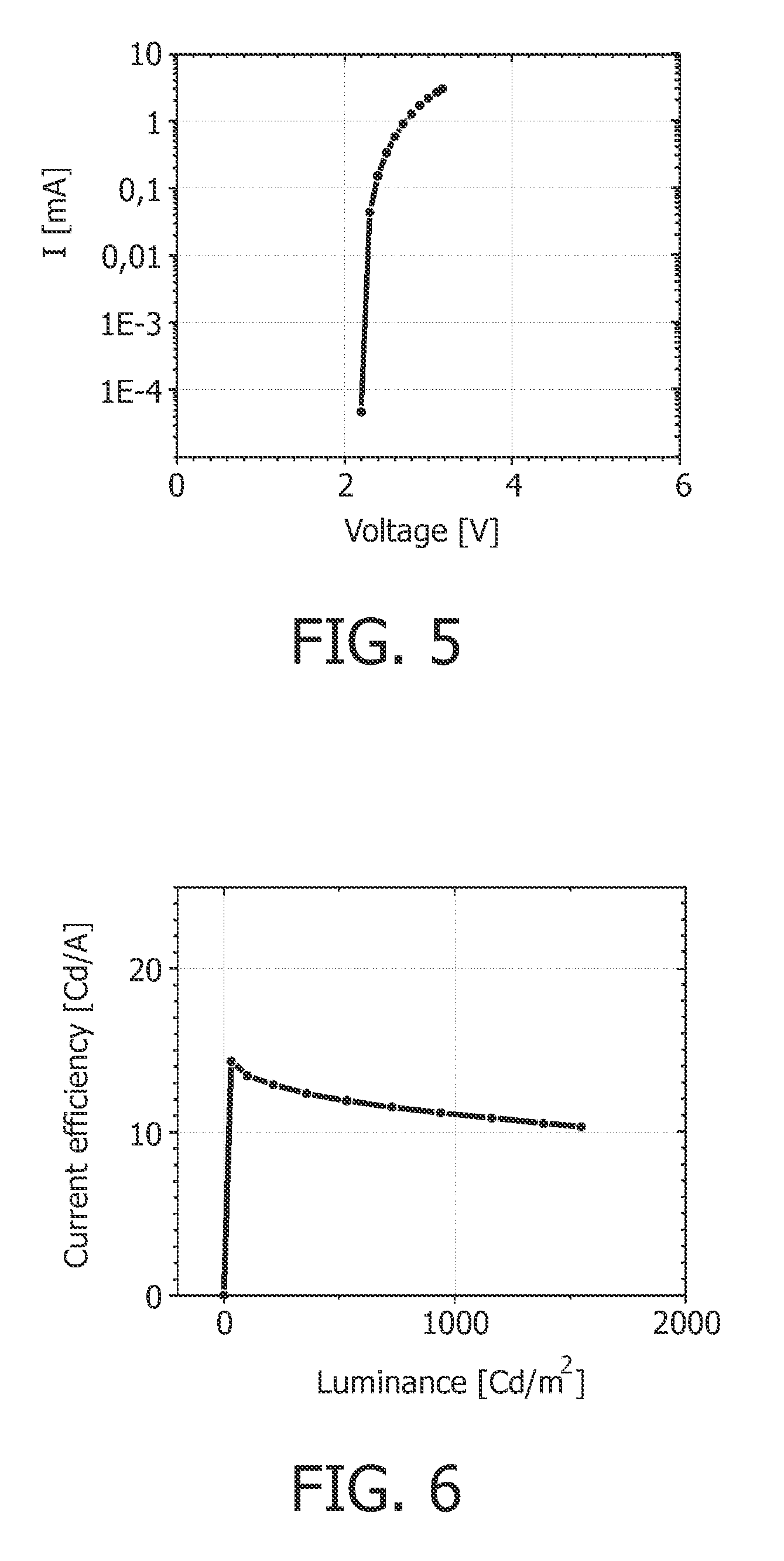
[0088]Emitter Ir(2t-tiaz) is doped into a matrix consisting of n-MTDATA. The detailed structure is shown in the table below. The triplet energy of Ir(2t-tiaz) is 17000 cm−1

TABLE 2OLED structure according to example 2.LayerMaterialthicknessAnodeITO120nmHole injection layerNHT1:NDP220nmHole transport layern-MTDATA10nmMatrix:Emittern-MTDATA:Ir(2t-25nmtiaz) 8 at %Electron transport layerTPBI10nmElectron injection layerNET5:NDN145nmCathodeAl100nmITO = Indium tin oxiden-MTDATA = 4,4′,4″-Tris(N-(1-naphthyl)-N-phenyl-amino)-triphenylamineTPBI = 1,3,5-tris-(1-phenyl-1H-benzimidazol-2-yl)-benzeneNHT1, NDP2, NET5, NDN1 are products of Novaled GmbH Dresden.NHT1:NDP2 is used to enhance inject of holes, andNET5:NDN1 is used to enhance injection ofelectrons into the OLED device.Formula 3: Structure of the emitter used in example 2.

[0089]The OLED device according to example 2 has at 1000 Cd / m2 a current efficiency of 11.1 Cd / A, and a power efficiency of 11.9 lm / W.

example 3

[0090]Production of an inventive triphenylene derivative of the formula (IIb) according to Scheme 3:

Synthesis of 2-Triphenylene carbonic acid

[0091]Step a)

[0092]Triphenylene (1 equivalent) is at 0° C. reacted with 2,1 equivalents AlCl3 and 21,0 equivalents CH3COCl in CH2Cl2. After 3 h stirring at room temperature the product (Acetyltriphenylene) is got in 97% yield, which is further reacted in Step b).

[0093]Step b)

[0094]The product of Step a) is reacted with mit 2,2 equivalents I2 (based on the raw yield of Acetyltriphenylene) in Pyridin solvent at room temperature. Then, the mixture is kept for 45 min under reflux, afterwards another portion I2 (1,0 equivalent) is added. After another hour at reflux NaOH, EtOH and water are added and the reaction mixture is heated to reflux for 2 h. 2-Triphenylene carbonic acid is got in 76% yield (based on the raw yield of Acetyltriphenylene and in 74% yield based on Triphenylene).

[0095]Production of a Triphenylene derivative according to formula I...


PUM


Abstract

The present invention is directed to the field of organic light emitting diode (OLED) electroluminescent devices comprising a light-emitting layer containing an organic metal coordination compound with tailored ligands of the general structure (1) where (2) is a N-containing heterocycle comprising one or more cycle and where (3) is a unit with a triplet energy of at least 22,220 cm−1.

Description

FIELD OF THE INVENTION[0001]The present invention is directed to the field of organic light emitting diode (OLED) electroluminescent devices comprising a light-emitting layer containing an organic metal coordination compound with tailored ligands having a high triplet energy.BACKGROUND OF THE INVENTION[0002]While organic electroluminescent (EL) devices have been known for over two decades, their performance is generally limited due to several adverse effects. In its simplest form, an organic EL device is comprised of an anode for hole injection, a cathode for electron injection, and an organic medium sandwiched between these electrodes to support charge recombination that yields emission of light. These devices are commonly referred to as organic light-emitting diodes (OLEDs).[0003]In ordinary organic EL devices fluorescence caused during a transition of luminescent center molecules from a singlet excited state to a ground state is used as luminescence. However, only 25% of all exci...

Claims


Application Information

Patent Timeline
Patent Type & Authority Applications(United States)
IPC IPC(8): H01J1/62
CPCC09K11/06C09K2211/1029C09K2211/185H01L51/0085H01L51/5016H05B33/14H10K85/342H10K50/11H10K2101/10
Inventor BOERNER, HERBERT FRIEDRICHLOEBL, HANS-PETERSALBECK, JOSEFPOPOVA, ELENA
Owner KONINKLIJKE PHILIPS ELECTRONICS NV
Why Eureka
Try Eureka