Miniature high voltage/current ac switch using low voltage single supply control

a high-voltage/current ac switch and control technology, applied in the direction of power conversion systems, safety/protection circuits, electrical equipment, etc., can solve the problems of only being able to power extremely low-power devices, only extending battery life, and insufficient efficiency and power delivery to fully charge even a typical portable device. , to achieve the effect of preventing any heating issues, improving power delivery to the other receiver or receiver, and high efficiency

Inactive Publication Date: 2010-05-06
UNIV OF FLORIDA RES FOUNDATION INC
View PDF2 Cites 144 Cited by
  • Summary
  • Abstract
  • Description
  • Claims
  • Application Information

AI Technical Summary

Benefits of technology

[0008]Embodiments of the invention relate to a method and a high-efficiency wireless power transfer system that is capable of supporting more than one receiver via inductive coupling. The wireless power transfer system can use a class E operation for the transmitter and a decoupling switch. The system can operate without a complex external control system, by relying on the system's natural impedance response to achieve the desired power delivery profile across a wide range of load resistances, while maintaining high efficiency to prevent any heating issues. A switch architecture can be used to “decouple” the fully charged receiver or from the system so that power delivery to the other receiver or receivers can be improved. The system can be designed to deliver power to portable electronics, such as cellular phones, PDA's, mp 3 players. A specific embodiment of the subject system is compact and capable of nearly 2.5 W of power delivery to each of the two receivers in a dual receiver setup, and capable of delivering 5W to a single receiver alone or to a receiver when the other receiver is “decoupled” by a receiver switch. During high power delivery state, the system efficiency can be kept between 67.5% and 77.5%. Higher power delivery can be achieved by increasing the supply voltage and using higher power components.

Problems solved by technology

Attempts have been made to achieve long range power delivery via far-field techniques have not been successful.
The efficiency and power delivery is insufficient to fully charge even a typical portable device overnight at a comfortable distance.
Such systems are only viable for extending battery life or to power extremely low power devices such as Zigbee sensor nodes.
In order to provide power comparable to a typical wall mounted DC supply, the system would violate RF safety regulations (IEEE Std C95.1, 2005 Edition, IEEE Standard for Safety Levels with Respect to Human Exposure to Radio Frequency Electromagnetic Fields, 3 kHz to 300 GHz), or has to use a large number of transmitters resulting in an impractical and costly implementation.
Its operating range is limited as power delivery and efficiency degrades rapidly with increasing distance between the transmitting and receiving unit.
Using near-field operation at frequencies below 1 MHz significantly lowers the probability of interference and RF safety issues since the wavelength is extremely long and radiation is limited.
However, unlike far-fields techniques, near-field techniques are extremely sensitive to the loading the condition of the receiver(s) as well as the number of receivers.
Limited studies have been done on analyzing the power delivery of an inductive coupling system to multiple receiving units via a single transmitting unit.
Therefore, it is commonly considered important to keep the operation of the Class E transistor within its operational bounds as any significant deviation may lead to failure of the transmitter.
Delivering power to a device with a high efficiency switching regulator at the input of the device can be challenging.
Poor efficiency will be observed due to excess power dissipated as heat and device failure may occur due to over voltage.
In addition, developing a robust control system to avoid the bifurcation phenomena [12-14] can increase the complexity of the system significantly.
A planar wireless power system that is powering multiple loads might not be able to deliver sufficient power to all devices to maintain the nominal charge rate, especially when one or more of the devices is fully charged.
This in turn may cause the other devices to charge slower.
This can make the circuit large, complicated, and costly.

Method used


Image

  • Miniature high voltage/current ac switch using low voltage single supply control
  • Miniature high voltage/current ac switch using low voltage single supply control
  • Miniature high voltage/current ac switch using low voltage single supply control

Examples


example 1

A Class E Transmitter System

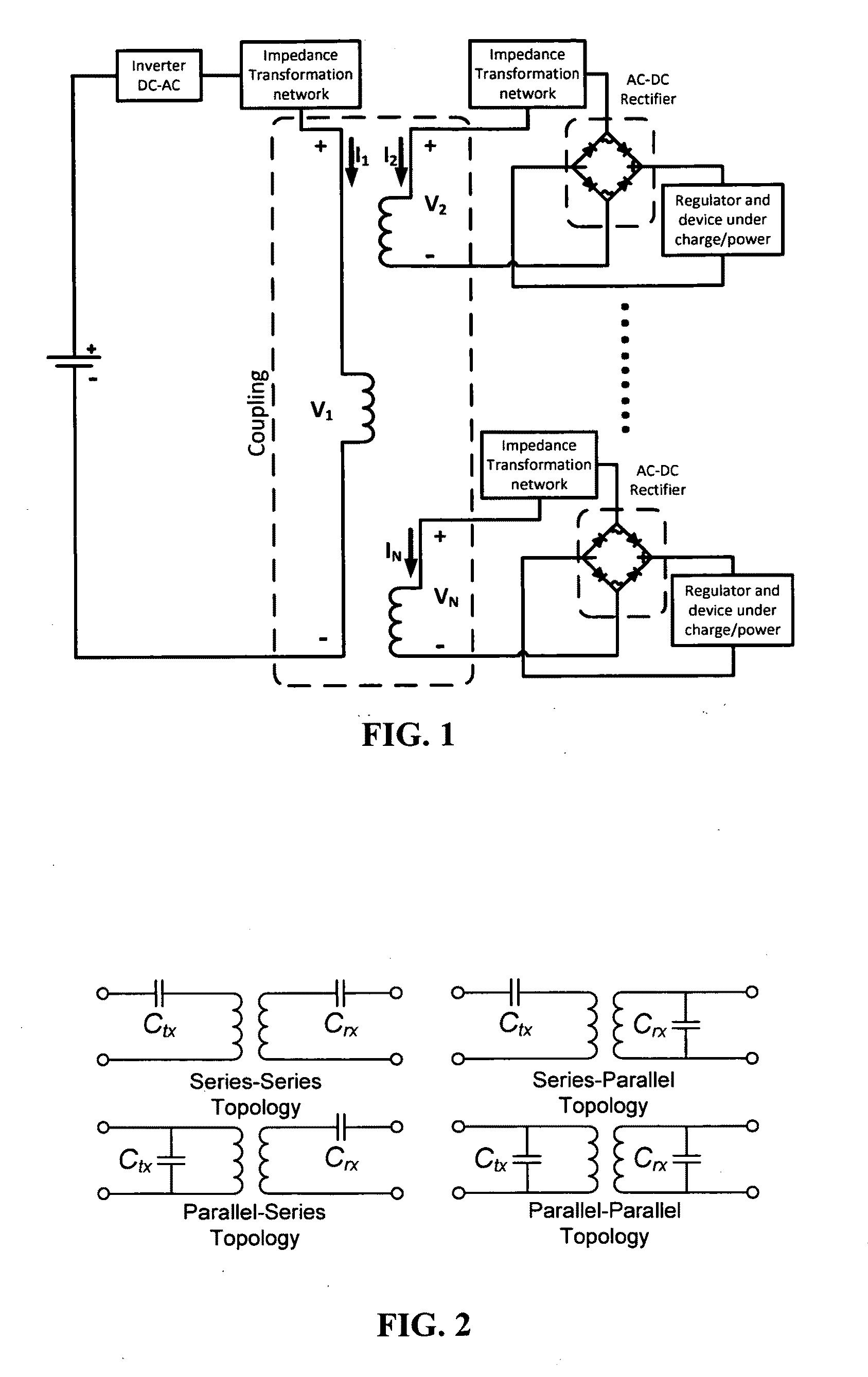
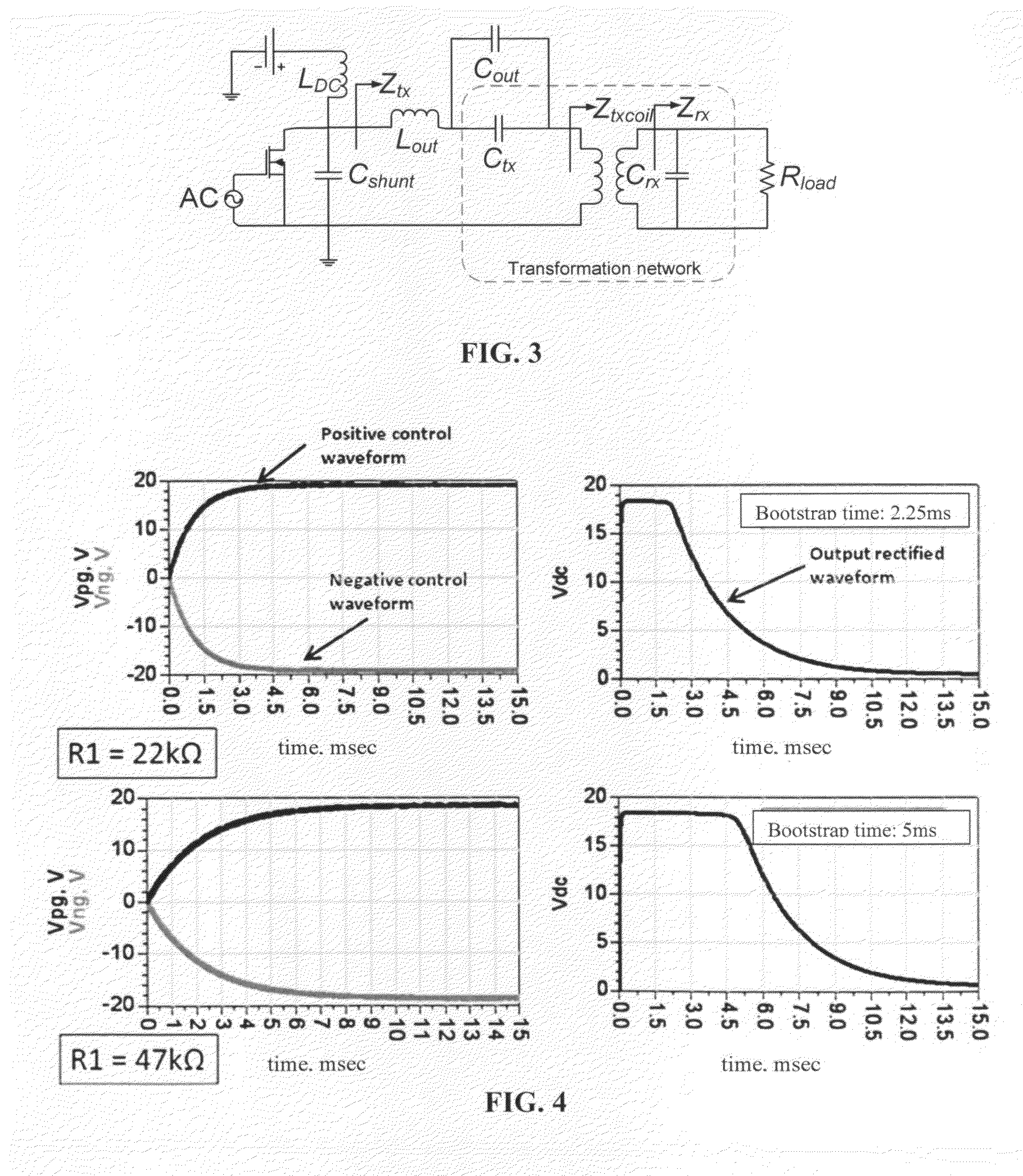
[0102]A Class E transmitter system using the IRLR / U3410 HEXFET® power MOSFET rated at 100V breakdown voltage from International Rectifier. A half wave rectifier with a shunt charge holding capacitor of 4.7 μF at the output using MBRA340T3 from ON Semiconductor is used to convert the AC power to DC power. Since the forward voltage drop is 0.45V and the reverse recovery is negligible, power loss due to the voltage drop and reverse recovery is small compared to the amount of power delivered to the load. Load resistance in this section can be assumed to be the equivalent resistance looking into the regulator or device being charged or powered as shown in FIG. 1 instead of the equivalent resistance looking into the rectifier as shown in FIG. 3.

[0103]A Matlab code is written based on the equations derived in [19]-[20] to study the power delivery. Instead of using the calculated value, the value used for the power delivery simulation can be actual values used fo...


PUM


Abstract

Embodiments of the invention pertain to a method and apparatus for planar wireless power transfer where the receiver switches off and / or performs a duty cycle. In an embodiment, the switch can be used in a system that having a high voltage / current solid state switch, without having a high voltage control signal. An embodiment provides a switch that is capable of breaking, or greatly reducing, the connection of the receiver coil and the receiver circuitry in order to enable the receiver to decouple from the power transfer system. This embodiment can allow the transmitter to put out more power to other devices without providing power to the switched device. When the switch is used for a fully charged device, the switching can prevent or reduce damage to the fully charged device.

Description

BACKGROUND OF INVENTION[0001]Recently, the emergent of various wireless power technology to eliminate the “last cable” has generated significant research interest. Wireless power systems can be classified into two main categories, medium to long range, where the coverage is greater or equal to a typical Personal Area Network (PAN), and short range, where the coverage is localized within the vicinity of the transmitting device (typically a 5″ distance). Attempts have been made to achieve long range power delivery via far-field techniques have not been successful. The efficiency and power delivery is insufficient to fully charge even a typical portable device overnight at a comfortable distance. Such systems are only viable for extending battery life or to power extremely low power devices such as Zigbee sensor nodes. In order to provide power comparable to a typical wall mounted DC supply, the system would violate RF safety regulations (IEEE Std C95.1, 2005 Edition, IEEE Standard for...

Claims


Application Information

Patent Timeline
Patent Type & Authority Applications(United States)
IPC IPC(8): H02M7/217
CPCH02J5/005H02J50/10H02J50/40H02J7/025H02J7/0029H02J50/12
Inventor LIN, JENSHANLOW, ZHEN NING
Owner UNIV OF FLORIDA RES FOUNDATION INC
Why Eureka
Try Eureka