
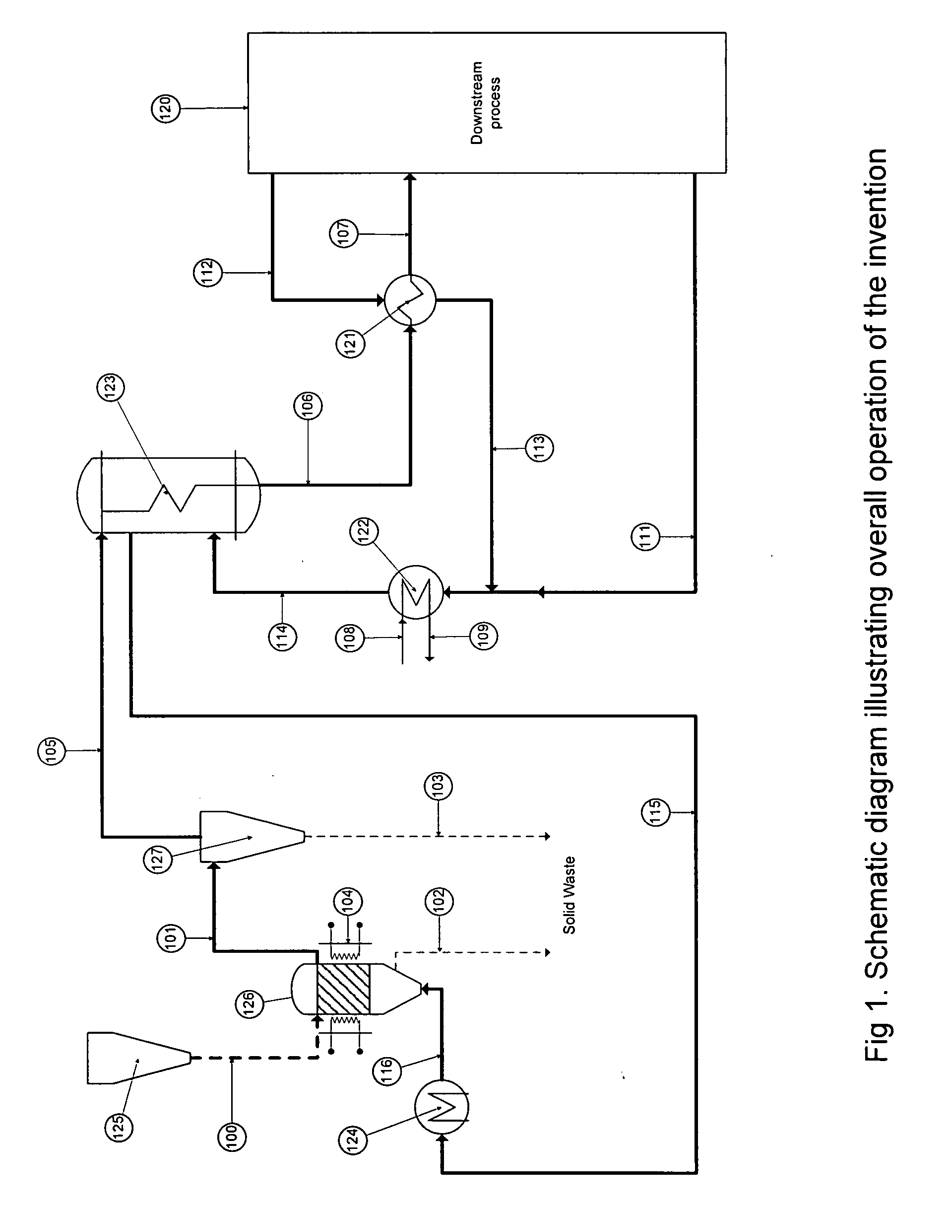
Apparatus and process for hydrogenation of a silicon tetrahalide and silicon to the trihalosilane

a technology of trihalosilane and hydrogenation apparatus, which is applied in the direction of silicon compounds, lighting and heating apparatus, furnaces, etc., can solve the problems of increasing capital cost and operating cost, increasing capital cost, and increasing capital cost, so as to improve heat integration, increase reaction rate, and increase the yield of trihalosilane

Active Publication Date: 2010-05-06
LORD LTD LP
View PDF10 Cites 13 Cited by
  • Summary
  • Abstract
  • Description
  • Claims
  • Application Information

AI Technical Summary

Benefits of technology

[0007]Systems incorporating the invention provide higher yield of the trihalosilane, lower fabrication cost lower cost of operation, high consumption of feed silicon flexible size distribution requirements for the feed metallurgical grade silicon and a flexible operation.
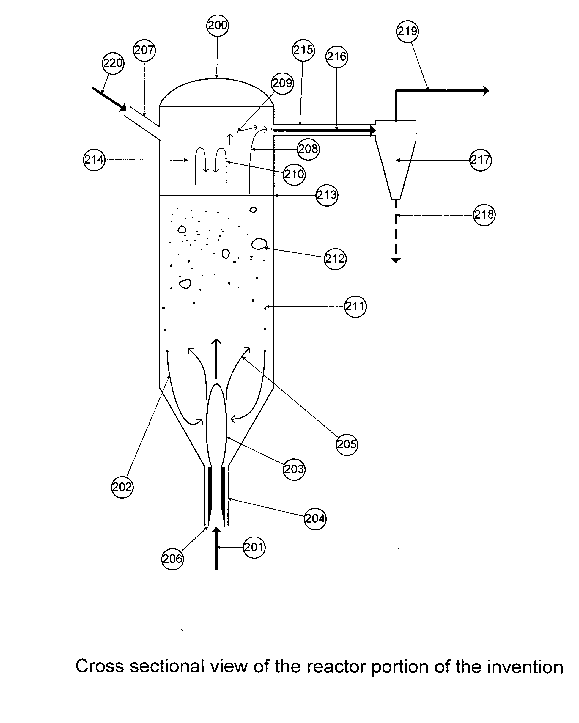
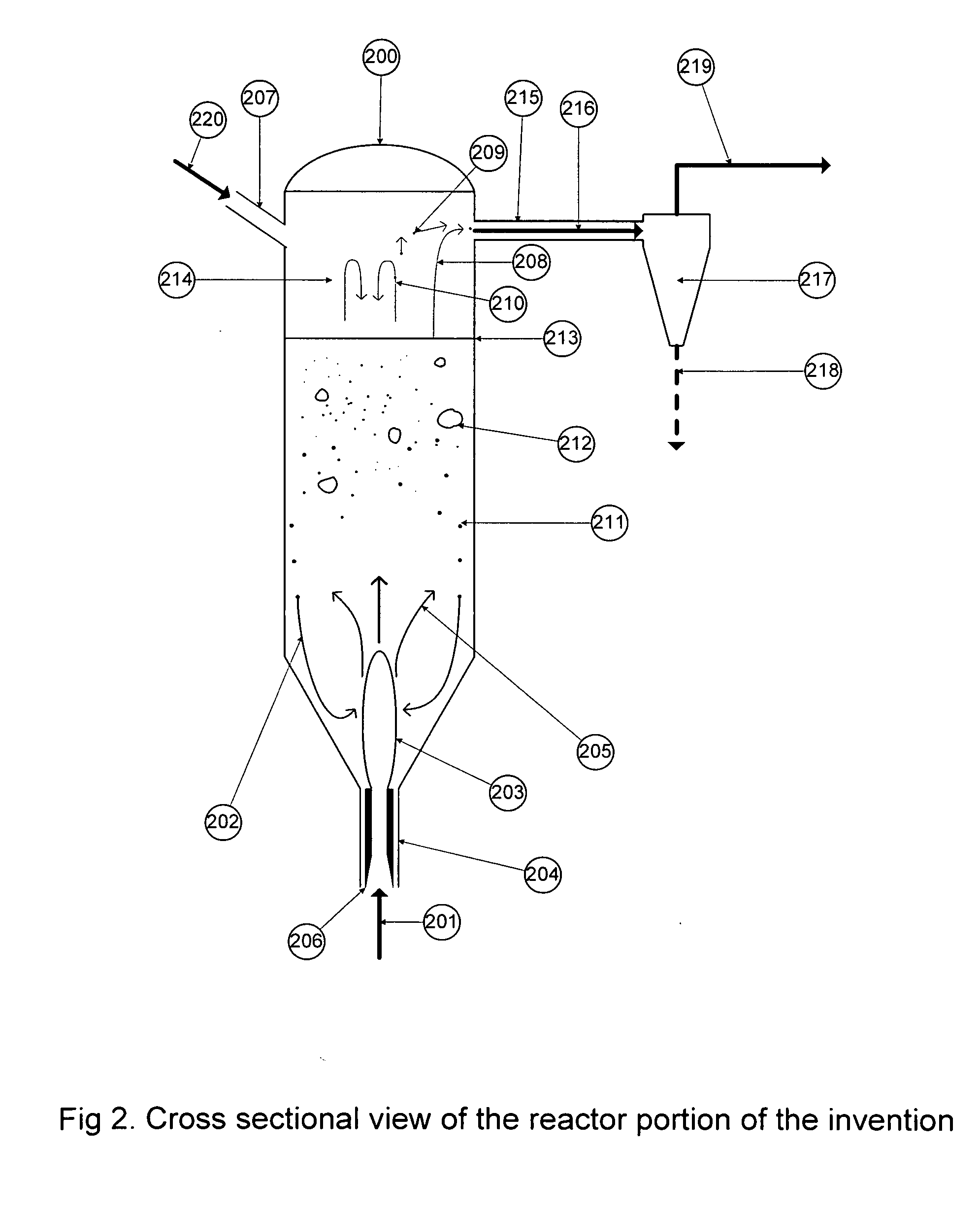
[0009]In accordance with a preferred embodiment of the invention, an apparatus for hydrogenation of a silicon tetrahalide and silicon to trihalosilane comprises: a vessel with no internal flow distribution, one or more gas entries, one or more solids entries, one or more solids drains, one or more gas / solids exits and fresh surface generation by jet grinding. Also further disclosed is a process for choosing a set of operating conditions to take full advantage of the apparatus and an example of improved heat integration. This apparatus has the advantages of higher reaction rates, higher yields of trihalosilane and lower capital and operating costs by better heat integration with the remainder of the process.

Problems solved by technology

Delaying the mixing to the mixing plenum increases the capital cost and operating cost because it makes heat recovery from the hot effluent gases more difficult and causes operational problems.
The silicon tetrahalide frequently contains significant traces of the trihalosilane and dihalosilane which can decompose to silicon inside the tetrahalide heaters causing plugging.
Using two separate preheaters increases the capital cost compared to a single train and makes it more difficult to recover heat from the exhaust gas which increases the use of utilities.
The provision of a distribution means increases capital cost.
The lower yield of commercial reactors can be attributed to the design of the distribution means and selection of typical fluidized bed operating conditions which cause bypassing of the silicon by large bubbles of reacting gas which means some of the reacting gas has a very short residence time.
The comminution increases reaction rate and yield but the Bade method of using a ball mill makes it difficult and expensive to implement at the high pressure, 500 psig, and high temperature, 500° C., needed for this reaction.

Method used


Image

  • Apparatus and process for hydrogenation of a silicon tetrahalide and silicon to the trihalosilane
  • Apparatus and process for hydrogenation of a silicon tetrahalide and silicon to the trihalosilane
  • Apparatus and process for hydrogenation of a silicon tetrahalide and silicon to the trihalosilane

Examples


example 1

[0028]The gas inlet composition is as in Table 1

[0029]ε is the voidage at Umb=0.4

[0030]g is the acceleration of gravity=980 m / s2

[0031]Dp is the diameter of the particle=To be calculated

[0032]ρp is the particle density=2.33 g / cc

[0033]ρf is the fluid density=0.0218 g / cc

[0034]μf is the viscosity of the fluid=0.00024 poise

[0035]U is the max. superficial velocity=0.11 m / sec=Umb

Therefore the desired minimum average particle size=444 microns. Since MGS is quite angular this particle size should be adjusted by dividing by the sphericity which is typically about 0.86. This gives the average particle size, 516 microns as measured by sieve analysis. Further standard population balance calculations can be made to allow for the shrinkage of the particle due to reaction and the decrease in size due to attrition to arrive at the required minimum average particle size for the feed to the reactor. Once a reasonable estimate has been obtained for the correct particle size for the feed, a test may b...

example 2

[0036]A reactor 10 meters long was charged with a 7 m high bed using MGS of a nominal 750 micron size. The reactor was run for 120 hours under the conditions of Table 1 and batches of metallurgical grade silicon] were added once per hour to maintain level. At the end of the run a sample of the MGS in the bed was taken from the bed and analyzed and the results are shown below.

TABLE 2Weight % of Particles in a sieve size rangeSieve sizeParticleMicronsWt % 0-500.03% 50-1000.24%100-1500.61%150-2000.96%200-2500.94%250-3002.44%300-3505.16%350-4003.85%400-4505.49%450-5007.53%500-55010.02%600-60013.01%650-65014.88%650-70016.52%700-75015.24%750-8003.08%

The average particle size was calculated at 538 microns

[0037]While the invention has been described in connection with a preferred embodiment, it is not intended to limit the scope of the invention to the particular form set forth, but on the contrary, it is intended to cover such alternatives, modifications, and equivalents as may be included...


PUM

PropertyMeasurementUnit
velocityaaaaaaaaaa
velocityaaaaaaaaaa
particle sizeaaaaaaaaaa

Abstract

A reactor for hydrogenation of a silicon tetrahalide and metallurgical grade silicon to trihalosilane includes a bed of metallurgical silicon particles, one or more gas entry ports, one or more solids entry ports, one or more solids drains and one or more ports for removing the trihalosilane from the reactor. Fresh surfaces are generated on the bed particles by internal grinding and abrasion as a result of entraining feed silicon particles in a silicon tetrahalide / hydrogen feed stream entering the reactor and impinging that stream on the bed of silicon particles. This has the advantages of higher yield of the trihalosilane, higher burnup rate of the MGS, removal of spent MGS as a fine dust carryover in the trihalosilane effluent leaving the reactor and longer times between shutdowns for bed removal.

Description

BACKGROUND OF THE INVENTION[0001]This invention relates generally to the field of high purity silicon production and more specifically to an apparatus and process for hydrogenation of a silicon tetrahalide and silicon to trihalosilane.[0002]Trihalosilanes such as SiHCl3 and SiHBr3 were first made by the reaction of silicon with the respective hydrogen halide, HCl or HBr, at a temperature of approximately 350° C. and at approximately atmospheric pressure. Yields from this reaction are typically very high, the literature showing yields in excess of 90%, with the remainder being silicon tetrahalide. The trihalosilane most commonly used is trichlorosilane which is purified and decomposed to form very pure silicon. This decomposition reaction also forms the silicon tetrahalide which thus builds up in the process. Various measure have been taken to minimize the production of silicon tetrahalide such as recycling the tetrahalide and using a large excess of hydrogen in the decomposition rea...

Claims


Application Information

Patent Timeline
Patent Type & Authority Applications(United States)
IPC IPC(8): C01B33/107B01J3/04
CPCB01J8/1827B01J8/24C01B33/1071C01B33/10773
Inventor LORD, STEPHEN MICHAEL
Owner LORD LTD LP
Learn More