[0004]This object can be achieved by providing an electrochemical energy source according to the
preamble, comprising at least one
electrochemical cell, each
cell comprising: a first
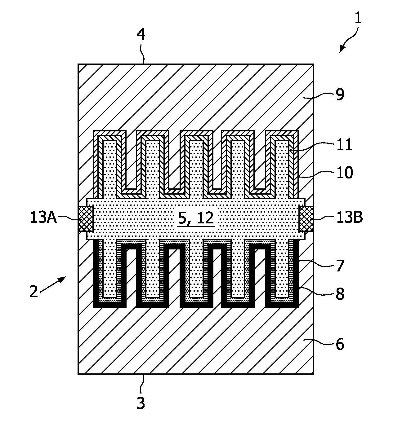
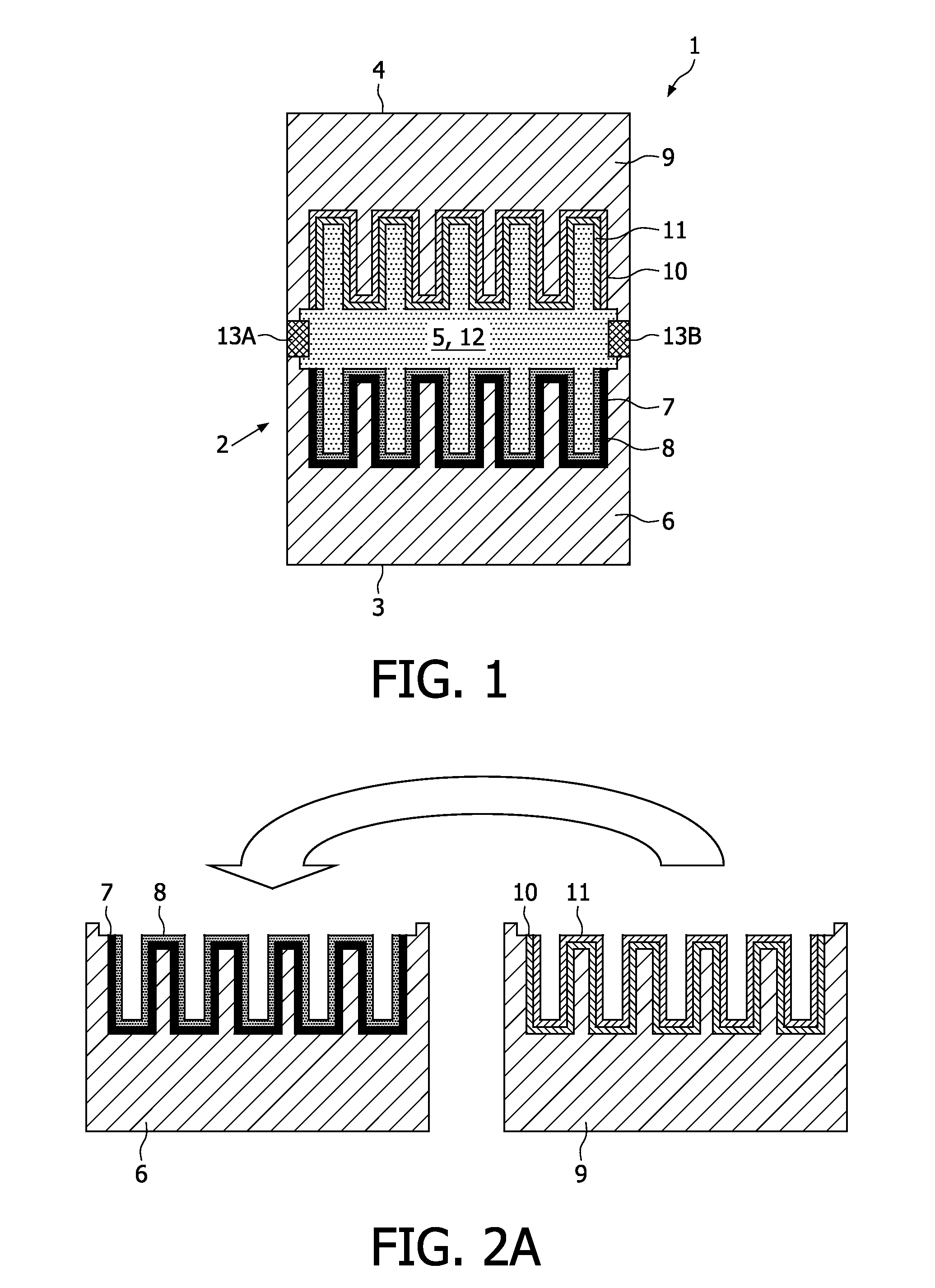
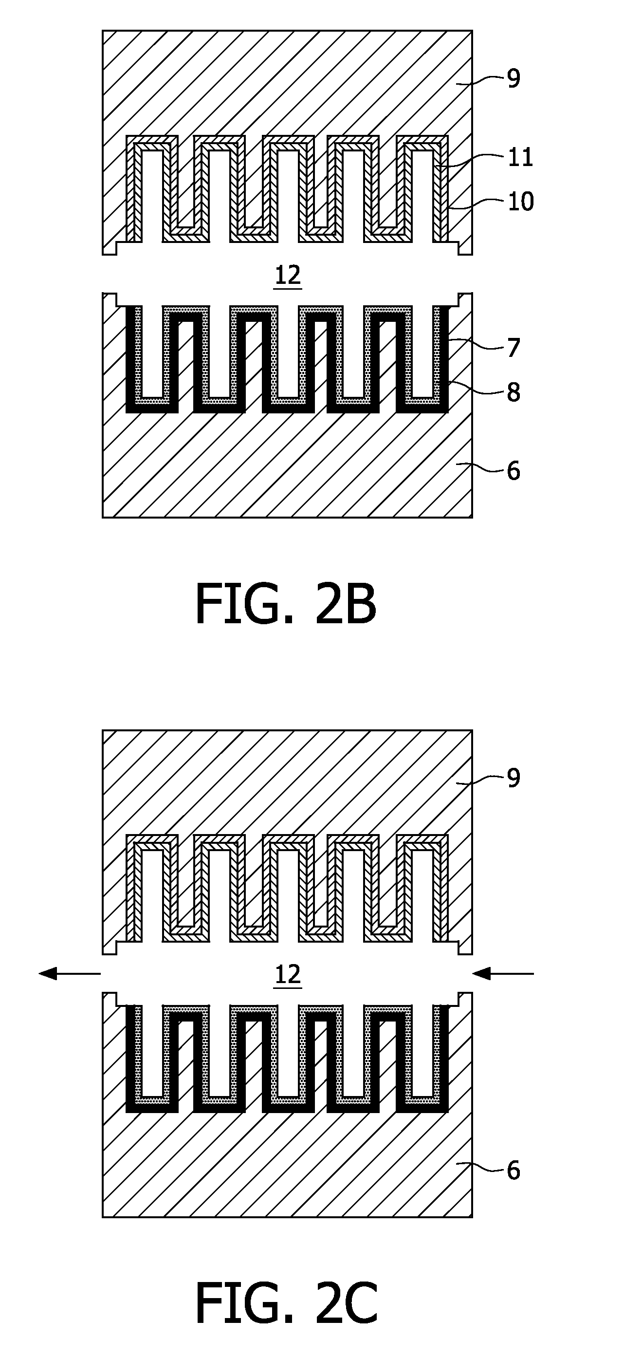
electrode deposited onto a first substrate, a second electrode deposited onto a second substrate, and an
electrolyte applied in a receiving space formed between said first electrode and said second electrode. Preferably the second electrode faces the first electrode, to allow a
flip chip arrangement of
cell parts as will be elucidated hereinafter. By depositing the different electrodes onto (commonly) different substrates the electrochemical energy source can be manufactured in a relatively efficient manner, since both electrodes can be deposited and annealed onto different substrates simultaneously, which leads to a considerable saving of manufacturing time. After this deposition step both
cell parts can be flip chipped, as a result of which the electrodes will be directed towards each other at a distance from each other. The receiving cavity present between the electrodes will subsequently be filled with the
electrolyte. Although expected to be less practical and hence less efficient it would also be conceivable that the first substrate and the second substrate are formed by the same (joint) substrate, wherein both electrodes are deposited aside to each (and not on top of each other), as a result of which both electrodes can still be deposited simultaneously onto the substrate to achieve the
advantage of saving of manufacturing time. In this latter case, a
flip chip of the (joint) substrate is not necessary to realise the electrochemical energy source according to the invention. Moreover, since both electrodes will be deposited separate from each other, matching of the electrode materials will be significantly less critical compared to the situation in which different layers are deposited on top of each other successively. Gearing the annealing temperatures of the different electrodes is hence not necessary to prevent degradation, and in particular
decomposition, of (layers of) the
electrochemical cell during annealing of the electrodes. Hence, the electrode materials can be chosen independently from each other and such, that the functionality of these materials to serve as electrode can be optimised in a relatively simple though efficient manner. The first electrode commonly comprises a
cathode, and the second electrode commonly comprises an
anode (or vice versa). Each electrode commonly also comprises a
current collector. By means of the current collectors the cell can easily be connected to an electronic device. Preferably, the current collectors are made of at least one of the following materials: Al, Ni, Pt, Au, Ag, Cu, Ta, Ti, TaN, and
TiN. Other kinds of current collectors, such as, preferably doped,
semiconductor materials such as e.g. Si, GaAs, InP may also be applied.
[0005]In a preferred embodiment at least one electrode is provided, and more preferably multiple electrodes are provided, with an increased contact surface area facing the electrolyte. In this manner the effective contact surface area between the electrolyte and the electrode(s) is increased substantially with respect to a conventional smooth contact surface of the electrodes, resulting in a proportional increase of the rate capability of the electrochemical energy source according to the invention. Since the contact surface area between both electrodes and the electrolyte may be increased independently from each other, the overall contact surface area, and hence the overall rate capability of the electrochemical energy source according to the invention can be optimised in a relatively efficient manner. Since each
electrode material commonly has specific reaction
kinetics related characteristics, the pattern of each electrode can be optimised to match the overall reaction
kinetics of both electrodes in a relatively accurate manner. This will be considerably beneficial in case a ((re)chargeable)
electrochemical cell is required which is intended to operate long-lastingly in a stable manner.
[0007]In a preferred embodiment the receiving space is at least partially filled with a liquid-state electrolyte. A major
advantage of the liquid-state electrolyte is that an intensive and durable contact of the electrolyte with the electrodes, and in particular with a surface of the electrodes having an increased contact surface area can be achieved, as a result of which the performance of the electrochemical energy source according to the invention can be optimised. Another important
advantage of applying a liquid-state electrolyte is that liquid-state electrolytes have a relatively high
ionic conductivity compared to solid-state electrolytes, which will be beneficial for the impedance of the electrolyte leading to, amongst others, an improved rate capability. Examples of liquid-states electrolytes are
lithium salt solutions, wherein e.g. LiClO4, LiPF6, and / or LiAsF6 can be dissolved in propylenecarbonate, di-ethylcarbonate, ethylenecarbonate, and / or di-methylcarbonate. Other liquids which could serve as liquid-state electrolyte are
room temperature molten salts, also known as ionic liquids. An
ionic liquid is a salt in which the ions are poorly coordinated, which results in these solvents being liquid below 100° C., or even at
room temperature (
room temperature ionic liquids, RTIL's). At least one
ion has a delocalized charge and one component is organic, which prevents the formation of a stable
crystal lattice. Methylimidazolium and
pyridinium ions have proven to be good starting points for the development of ionic liquids. Properties, such as
melting point,
viscosity, and
solubility of starting materials and other solvents, are determined by the substitutes on the
organic component and by the counter
ion. Many ionic liquids have even been developed for specific synthetic problems. For this reason, ionic liquids have been termed “designer solvents”. In case of the application of a liquid-state electrolyte, filling of the receiving space by the electrolyte will commonly be relatively simple. Eventually an underpressure can be applied within the receiving space to actively suck the electrolyte into the receiving space. To prevent leakage of the liquid-state electrolyte out of the receiving space, it is commonly advantageous to apply sealing means to seal the receiving space. Instead of liquid-state electrolytes, it is also imaginable to apply gel-type electrolytes, which are also very suitable to be impregnated into the receiving space between both electrodes. Gel-type electrolytes can be prepared mixing a liquid-state electrolyte as set out above with a
polymer, such as PMMA, PVP, to make the electrolyte more viscous, commonly provided that the
polymer is adapted to be dissolved in relatively high concentrations in the
solvent used.

