
Antireflective Coating Composition Comprising Fused Aromatic Rings

a technology of aromatic rings and coating compositions, applied in coatings, photomechanical devices, instruments, etc., can solve the problems of back reflectivity, thin film interference effects and reflective notching, and changes in critical line width dimensions

Inactive Publication Date: 2010-05-13
AZ ELECTRONICS MATERIALS USA CORP
View PDF67 Cites 25 Cited by
  • Summary
  • Abstract
  • Description
  • Claims
  • Application Information

AI Technical Summary

Benefits of technology

[0008]where, Fr1 is a substituted or unsubstituted fused aromatic ring moiety with 3 or more aromatic rings, R′ and R″ are independently selected from hydrogen, C1-C4 alkyl, Z, C1-C4alkyleneZ and where Z is substituted or unsubstituted aromatic group, R1 is selected from hydrogen or aromatic moiety, and B is a substituted or unsubstituted cycloaliphatic moiety. The invention further relates to a process for imaging the present composition.

Problems solved by technology

Two major disadvantages of back reflectivity are thin film interference effects and reflective notching.
Thin film interference, or standing waves, result in changes in critical line width dimensions caused by variations in the total light intensity in the photoresist film as the thickness of the photoresist changes or interference of reflected and incident exposure radiation can cause standing wave effects that distort the uniformity of the radiation through the thickness.

Method used


Image

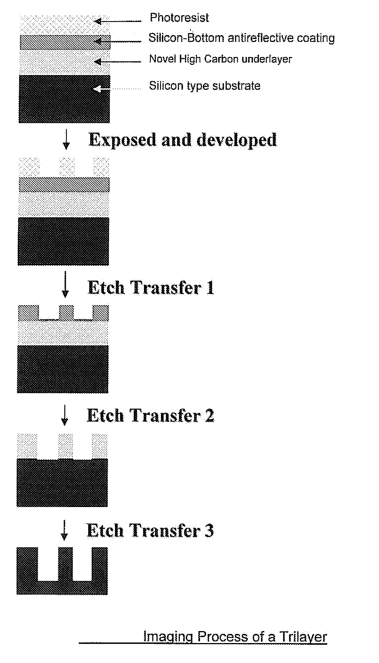
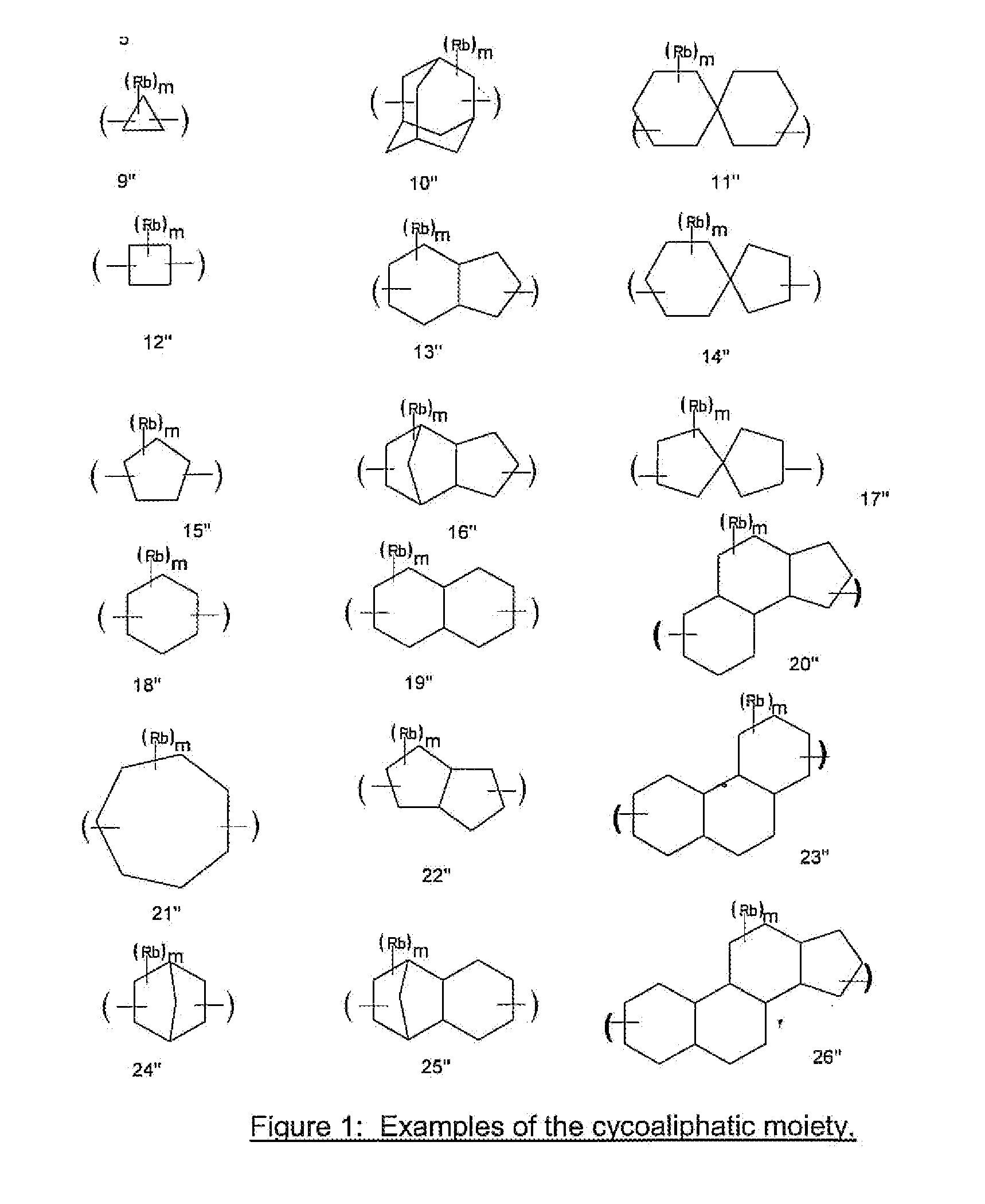
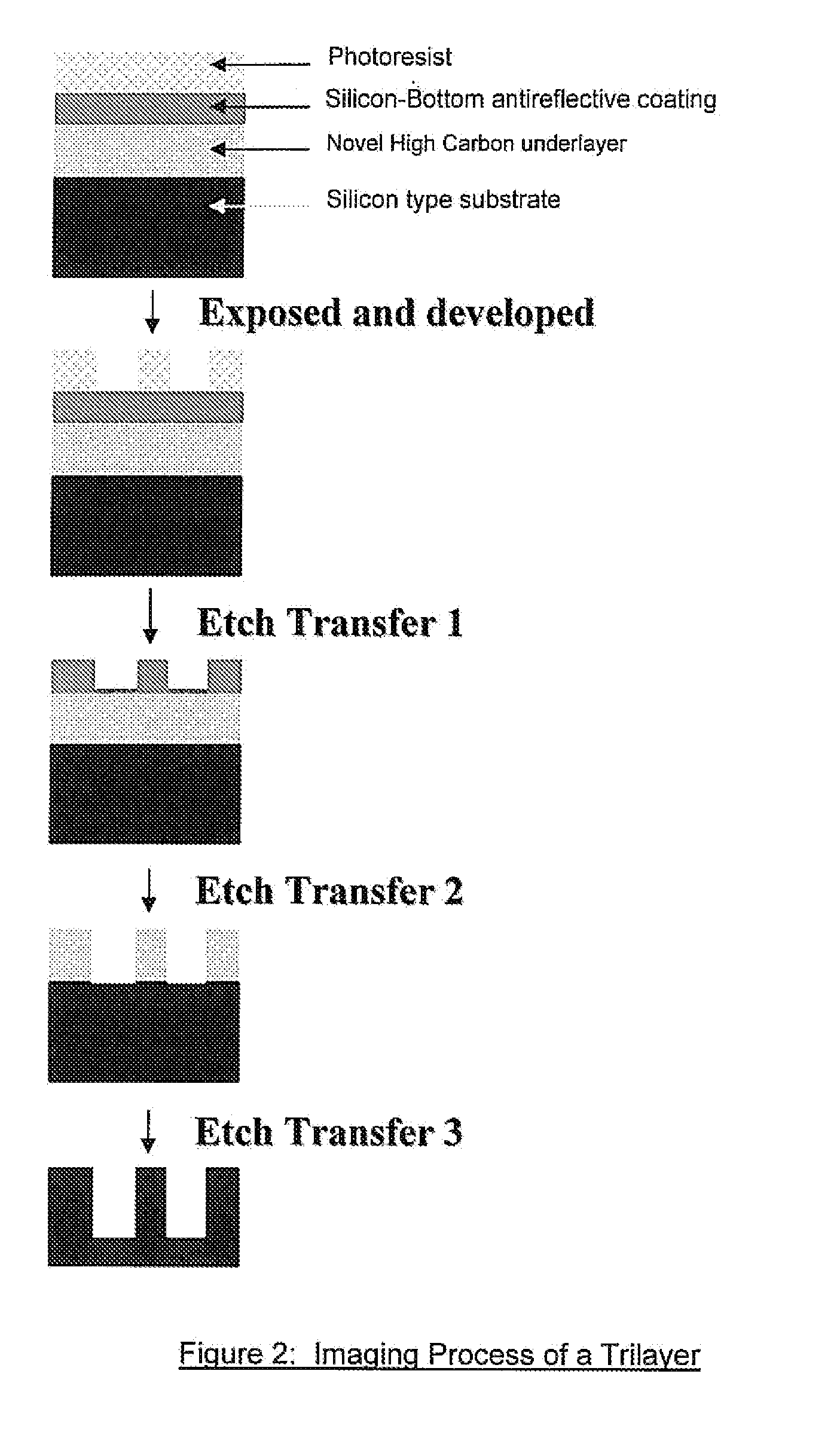
  • Antireflective Coating Composition Comprising Fused Aromatic Rings
  • Antireflective Coating Composition Comprising Fused Aromatic Rings
  • Antireflective Coating Composition Comprising Fused Aromatic Rings

Examples


example 1

Synthesis of Poly(anthracene-co-1-naphthol-co-phenol-co-adamantane-co-methylene).

[0047]Anthracene 26.7 g (0.15 mile), 1-naphthol 21.6 g (0.15 mole), phenol 28.2 g (0.30 mole), 1,3-adamantane diol 25.275 g (0.15 mole) and para formaldehyde (4.5 g (0.15 mole) and solvents diglyme 210 g and cyclopentylmethylether (CPME) 210 g were weighed together in a 1000 mL, 4 neck, round bottomed flask (RBF) equipped with overhead mechanical stirring, condenser, thermo watch, dean stark trap, and N2 purge. The components were mixed together at room temperature for 10 minutes and 5 g of triflic acid was added. It was mixed at room temperature for 5 minutes, and then the temperature set to 150° C. As the temperature increased, the water was removed from the reaction along with the CPME using the Dean Stark trap (240 mL). After 3 hours, the reaction was stopped and 1000 ml of CPME was added. The reaction mixture was transferred to a 5 liter flask, washed two times with 500 ml of deionized water. DI, w...

example 2

[0048]1.5 g of polymer from Example 1 was taken in a bottle, 0.15 g of TMOM-BP was added, 0.6 g of dodecylbenzene sulfonic acid, DBSA, at 10% solution in ArF-Thinner (70 PGME:30 PGMEA) was added and 12.75 g of ArF Thinner was added to make a 15.00 g of solution. After shaking overnight the formulation was filtered with a 0.2 μm filter.

example 3

[0049]n & k Measurement: The formulation from Example 2 was adjusted to 1.25% solid with ArF Thinner and the mixture was allowed to mix until all the materials become soluble. The homogeneous solution was filtered with 0.2 μm membrane filter. This filtered solution Was spin-coated on a 6″ silicon wafer at 1500 rpm, The coated wafer was baked on hotplate at 230° C. for 60 seconds. Then, n and k values were measured with a VASE Ellipsometer manufactured by J. A. Woollam Co. Inc. The optical constants n and k of the film for 193 nm radiation were, n=1.43, k=0.50


PUM

PropertyMeasurementUnit
temperatureaaaaaaaaaa
refractive indexaaaaaaaaaa

Abstract

The present invention relates to an organic spin coatable antireflective coating composition comprising a polymer where the polymer comprises (i) at least one unit with fused aromatic rings in the backbone of the polymer of structure (1), (ii) at least one unit with of structure (2), and, (iii) at least one unit with a cyclic aliphatic moiety in the backbone of the polymer of structure (3).where, Fr1 is a substituted or unsubstituted fused aromatic ring moiety with 3 or more aromatic rings, R′ and R″ are independently selected from hydrogen, C1-C4 alkyl, Z, C1-C4alkyleneZ and where Z is substituted or unsubstituted aromatic moiety, R1 is selected from hydrogen or aromatic moiety, and B is a substituted or unsubstituted cycloaliphatic moiety. The invention further relates to a process for imaging the present composition.

Description

FIELD OF INVENTION [0001]The present invention relates to an absorbing antireflective coating composition comprising a polymer with 3 or more fused aromatic rings in the backbone of the polymer, and a process for forming an image using the antireflective coating composition. The process is especially useful for imaging photoresists using radiation in the deep and extreme ultraviolet (uv) region.BACKGROUND OF INVENTION [0002]Photoresist compositions are used in microlithography processes for making miniaturized electronic components such as in the fabrication of computer chips and integrated circuits. Generally, in these processes, a thin coating of film of a photoresist composition is first applied to a substrate material, such as silicon based wafers used for making integrated circuits. The coated substrate is then baked to evaporate any solvent in the photoresist composition and to fix the coating onto the substrate. The baked coated surface of the substrate is next subjected to a...

Claims


Application Information

Patent Timeline
Patent Type & Authority Applications(United States)
IPC IPC(8): G03F7/00C08G61/00C08G65/00C08G63/02C08G16/00C08G16/02C08L65/00
CPCC08G10/02H01L21/0276G03F7/091C09D145/00C09D161/16H01L21/0274
Inventor RAHMAN, M. DALILMCKENZIE, DOUGLASANYADEIGWU, CLEMENT
Owner AZ ELECTRONICS MATERIALS USA CORP
Learn More