
Laser interferometer system for measuring roll angle

a technology of interferometer and roll angle, which is applied in the direction of interferometer, measurement device, instrument, etc., can solve the problems of high demand for surface quality of plane reflection mirror, complicated traditional method of interferometer measurement for roll angle, and inability to meet the requirements of measurement accuracy, etc., to achieve high precision, simple structure, and stable and reliable

Inactive Publication Date: 2010-06-10
UNIV OF SHANGHAI FOR SCI & TECH
View PDF4 Cites 28 Cited by
  • Summary
  • Abstract
  • Description
  • Claims
  • Application Information

AI Technical Summary

Benefits of technology

The present invention provides a high precision laser interferometer system for measuring roll angle with a simple and reliable structure. The system includes a laser source, a wedge prism assembly, a wedge mirror assembly, an optical interferometry assembly, and a phase detection assembly. The system works by producing two beams with different frequencies and polarizations, and then converting them into parallel beams through the wedge prism assembly. The beams are then reflected back to the optical interferometry assembly and recombined to produce an output beam. The system can provide accurate and reliable results even at small roll angles.

Problems solved by technology

Traditional method of interferometer measurement for roll angle is quite complicated, of which the key technique is using a plane reflection mirror in the same length as that of travel path and typically mounted on and moving with the moving body to be measured, incident beam from the source is reflected by this mirror and then detected by a photoelectric detector.
Methods like this can achieve high resolution, but suffer from various disturbances.
In this respect, U.S. Pat. No. 3,790,284 to R. R. Baldwin, entitled “Interferometer system for measuring straightness and roll” discloses an interferometer for measuring straightness and roll which application is however limited due to the requirement of two expensive Wollaston prism and difficult orientation of the target mirror to the Wollaston prism.
On the other hand, with above methods a high demand was made on the surface quality of the plane reflection mirror, which is not beneficial for lowering the cost.
Furthermore, the surface quality of the plane reflection mirror is subject to temperature and stress deformation, thus the reliability of the measurement is reduced.
86-91), however, the accuracy is affected by rotary drift.
Besides, a twofold magnification nearly means a one to one measurement of the geometrical rotating angle of the polarizer, thus a comparatively low resolution results.
Because the phase shift is not linear related to the change of the roll angle in this method, a calibration is required, which limits the precision of the system.
However, the roll angle change and the detected signal change do not have a linear relation, so a calibration is needed, thus the precision is limited.
However, there is need for reference mirror and calibration, and the sensitivity for light intensity detection suffers from the influences of the light source and the signal-to-noise ratio.
Furthermore, the precision of the measurement using two-point method (or three-point method) is limited by many factors.
These methods are time and effort consuming, and not practical for online measurement.

Method used


Image

  • Laser interferometer system for measuring roll angle
  • Laser interferometer system for measuring roll angle
  • Laser interferometer system for measuring roll angle

Examples


Embodiment Construction

[0023]A more detailed description of the objectives and preferred embodiment of the present invention is given below in combination with the drawings.

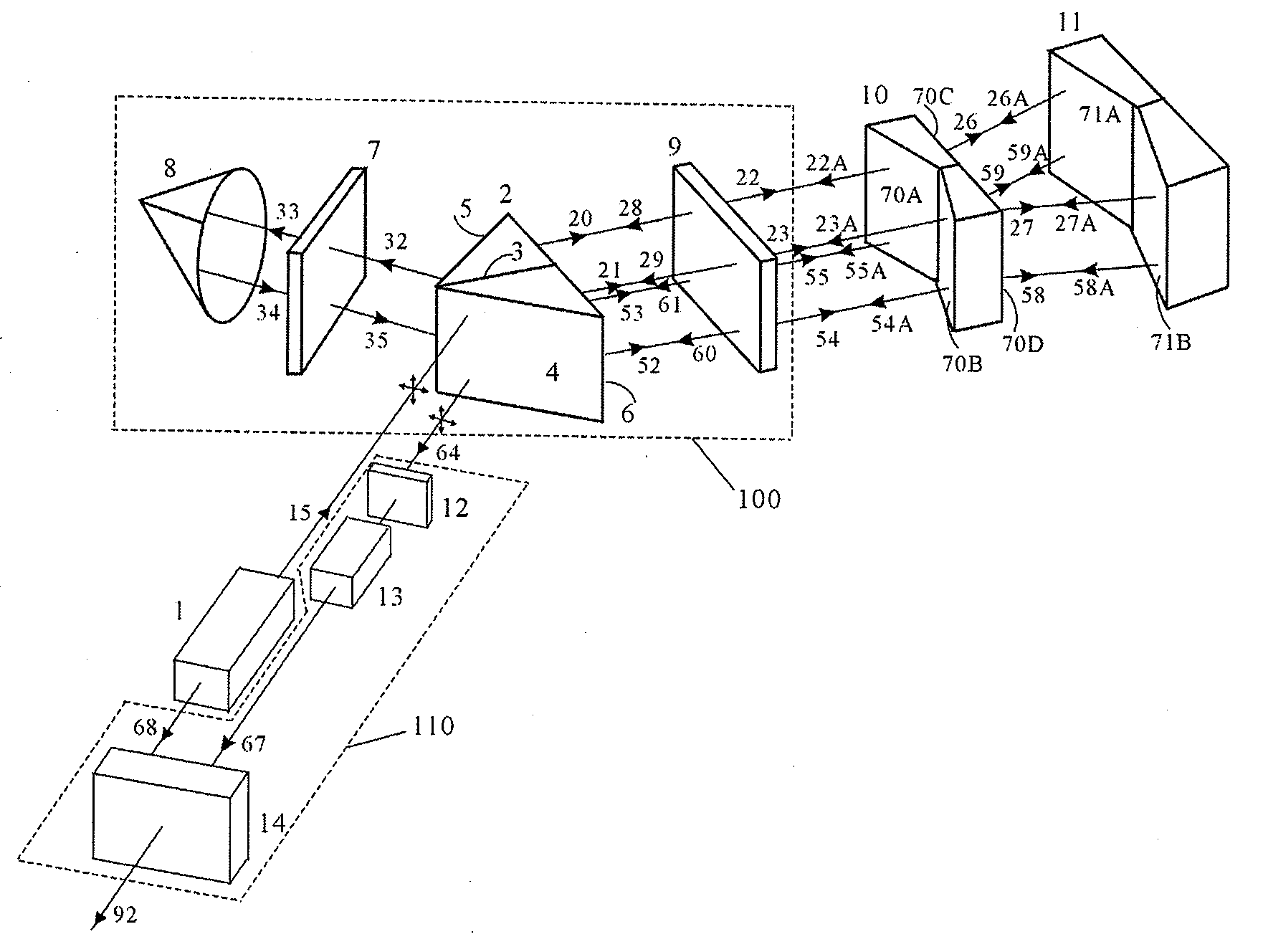
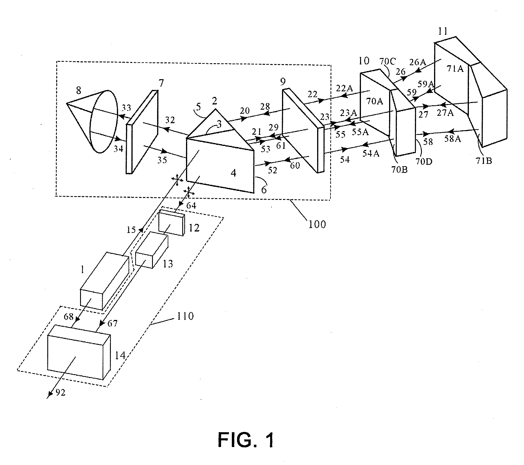
[0024]FIG. 1 is a schematic diagram of a preferred embodiment of the roll measuring interferometer system of the present invention. The system comprises laser source 1, optical interferometry assembly 100, wedge prism assembly 10, wedge mirror assembly 11, phase detection assembly 110.

[0025]The optical interferometry assembly 100 therein comprises polarizing beam splitting prism 2, quarter-wave plate 9, quarter-wave plate 7, and corner cube 8. The phase detection assembly comprises polarizer 12, photoelectric detector 13, and phase meter 14.

[0026]The laser source 1, a frequency stabilized laser, emits incident beam (15) with two linear orthogonally polarized components of different optical frequency which enter the polarizing beam splitting prism 2, and at the same time provides a stable electric reference signal with a frequency equal...


PUM


Abstract

A laser interferometer system for measuring roll angle around the direction of linear displacement comprises a light source of a frequency stabilized input beam (15) with two linear orthogonally polarized components which may or may not be of the same frequency, a polarizing beam splitting prism, two quarter-wave retardation plates, a corner cube retroreflector, a prism assembly, attached to the mechanical apparatus whose roll angle of travel is to be measured, a wedge mirror assembly, a polarizer, a photoelectric detector, and a phase meter; the light source emits a frequency-stable incident beam and generates a stable electric reference signal; under the actions of the polarizing beam splitting prism, quarter-wave plate and corner cube retroreflector, the incident beam travels twice through and then reflected twice by the wedge mirror assembly, and finally exits from the polarizing beam splitting prism. The polarizer mixes the orthogonal components of the output beam and the photoelectric detector generates an electric signal and then the phase meter compares the phase difference of said electric measurement signal with said electric reference signal, then the roll angle of travel can be measured. The advantage of present invention is: the system has simple structure but with high measurement precision, it can be applied to the precision geometrical measurement and the establishment of precision benchmark metrology in wide high-tech fields such as military industry, aerospace engineering and digital controlled machine tools.

Description

FIELD OF THE INVENTION[0001]The present invention generally relates to laser system for precision measurement and, more particularly, to a laser interferometer system for measuring roll angle, the rotation motion around the displacement axis.DESCRIPTION OF PRIOR ART[0002]The precision benchmark metrology and the precision measurement for geometrical quantities are important in high-tech fields such as military industry, aerospace engineering and digital controlled machine tools, among which especially the technique for measuring roll angle has received more and more attention, because for lack of suitable measuring method. Traditional method of interferometer measurement for roll angle is quite complicated, of which the key technique is using a plane reflection mirror in the same length as that of travel path and typically mounted on and moving with the moving body to be measured, incident beam from the source is reflected by this mirror and then detected by a photoelectric detector...

Claims


Application Information

Patent Timeline
Patent Type & Authority Applications(United States)
IPC IPC(8): G01B9/02
CPCG01B11/26G01B9/02019G01B9/02007G01B2290/15G01B9/02018G01B2290/70G01B9/02003
Inventor HOU, WENMEIZHAO, XIANBINZHANG, YUNBO
Owner UNIV OF SHANGHAI FOR SCI & TECH
Learn More