Thermoelectric nanowire array with low heat leakage and manufacturing method thereof

a technology of thermoelectric nanowires and nanowires, which is applied in the direction of superimposed coating process, liquid/solution decomposition chemical coating, lighting and heating apparatus, etc., can solve the problems of insignificant economic benefits, low efficiency of thermoelectric devices, and limited to small-scale applications, so as to reduce the thermal conduction property of template materials and improve the performance of thermoelectric nanowire arrays. , the effect of low thermal conductivity

Inactive Publication Date: 2010-07-01
IND TECH RES INST
View PDF6 Cites 17 Cited by
  • Summary
  • Abstract
  • Description
  • Claims
  • Application Information

AI Technical Summary

Benefits of technology

[0023]The efficacy of the present invention lies in that, nanowire array units separated from each other are formed on a substrate, and an air wall is formed at a region free of nanowire array units, so as to form a heat leakage barrier layer. Or, a polymeric material having a low thermal conductivity is combined with a template material so as to form a composite template structure for nanowires to deposit therein, so as to reduce the thermal conduction property of the template material. With the design of the air wall or the composite template structure of the present invention, the heat leakage phenomenon of the thermoelectric nanowire array is avoided, thereby greatly improving the performance of the thermoelectric nanowire array.

Problems solved by technology

However, currently seen thermoelectric devices have quite high costs with non-ideal efficiency and insignificant economic benefits, and thus are only limited to small-scale applications.
However, a single nanowire cannot be used in actual refrigeration / power generation applications, so that millions of nanowires must be gathered to transmit a sufficient amount of heat and electric current.
Therefore, how to arrange the huge number of nanowires regularly and maintain the mechanical strength is one problem pressing for solution currently.
For cooling application, the direction of thermal conduction is exactly opposite to the direction of the heat flow extracted by the Peltier effect, and thus a phenomenon of heat leakage (or referred to as parasitic heat of the thermoelectric material) is formed, which seriously reduces the working efficiency of the thermoelectric nanowire array.
Although the thermoelectric nanodevice structures in the above patent applications directly form the template and the nanowire array on a silicon substrate, the disadvantage of such kind of structure design lies in that, the template is completely contact with the silicon substrate.
In this way, heat leakage from template reduces the thermal removing efficiency of the thermoelectric nanodevice.

Method used


Image

  • Thermoelectric nanowire array with low heat leakage and manufacturing method thereof
  • Thermoelectric nanowire array with low heat leakage and manufacturing method thereof
  • Thermoelectric nanowire array with low heat leakage and manufacturing method thereof

Examples


third embodiment

[0048]An effective thermal conductivity equation of a composite template structured formed by combining the polymeric material 180 having a low thermal conductivity with the template material 130 disclosed in the present invention is as follows:

λeff=(1ϕtemplateλtemplate+ϕlowthermalconductivitymaterialλlowheatconductivitymaterial)

[0049]where, λtemplate is the thermal conductivity of the template material, λlow thermal conductivity material is the thermal conductivity of the polymeric material, φtemplate is the volume fraction of the template material, and φlow thermal conductivity material is the volume fraction of the polymeric material.

[0050]When the volume fraction of the polymeric material is high or the thermal conductivity of the polymeric material is low, the polymeric material becomes a dominant factor in the denominator of the above equation, thereby reducing the thermal conductivity of the composite template structure. Taking a Al2O3 porous template as an example, the therm...

second embodiment

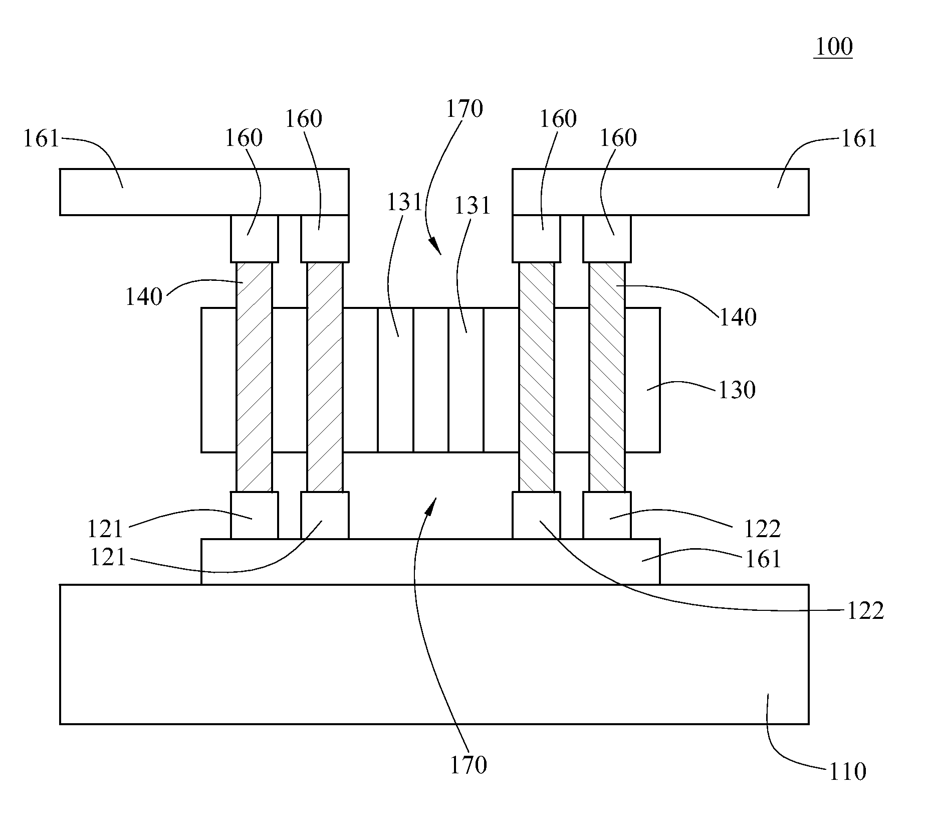
[0051]FIGS. 7 and 8 are schematic structural views of a thermoelectric nanowire array in different forms of the present invention. The difference between the thermoelectric nanowire array 100 shown in FIG. 7 and the structure of the second embodiment shown in FIG. 3L lies in that, no template material 130 exists between the N-type region 121 and the P-type region 122 of the first electrode 120, and a third electrode 161 is disposed between the N-type region 121 and the substrate 110 and between the P-type region 122 and the substrate 110. Therefore, after the process steps of forming the template material 130, the template material 130 between the N-type region 121 and the P-type region 122 is removed, such that the air wall 170 exists both between the first electrodes 120 and between the second electrodes 160, thereby effectively blocking the reflux phenomenon of thermal energy. In the thermoelectric nanowire array 100 shown in FIG. 8, the template material 130 at two ends of the n...


PUM

PropertyMeasurementUnit
thermoelectricaaaaaaaaaa
areaaaaaaaaaaa
thermal energyaaaaaaaaaa

Abstract

A thermoelectric nanowire array with a low heat leakage and a manufacturing method thereof are described. Nanowire array units separated from each other are formed on a substrate, and an air wall is formed at a region on the substrate free of the nanowire array units. Or, a polymeric material having a low thermal conductivity is combined with a template material so as to form a composite template structure for nanowires to deposit therein. With the design of the air wall or the composite template structure, the thermal reflow phenomenon of the thermoelectric nanowire array is avoided, thereby greatly improving a thermal dissipation efficiency of the thermoelectric nanowire array.

Description

CROSS-REFERENCE TO RELATED APPLICATIONS[0001]This non-provisional application claims priority under 35 U.S.C. §119(a) on Patent Application No(s). 097151825 filed in Taiwan, R.O.C. on Dec. 31, 2008 the entire contents of which are hereby incorporated by reference.BACKGROUND OF THE INVENTION[0002]1. Field of Invention[0003]The present invention relates to a nanowire array and a manufacturing method thereof, and more particularly to a thermoelectric nanowire array with a low heat leakage and a manufacturing method thereof.[0004]2. Related Art[0005]A heat transfer device has wide applications in various heating / cooling and power generation / heat recovery systems, for example, in fields such as refrigeration, air conditioning, electronic element cooling, industry temperature control, waste heat recovery, and power generation. The conversion between thermal energy and electric energy has been a manner of energy utilization currently, and the electronic-mechanical energy conversion has bec...

Claims


Application Information

Patent Timeline
Patent Type & Authority Applications(United States)
IPC IPC(8): F25B21/04B05D5/12C23C28/00
CPCC23C28/021C23C28/023
Inventor LEE, WEN-JIN
Owner IND TECH RES INST
Why Eureka
Try Eureka