
Method and system for controlling the amount of Anti-fouling additive for particulate-induced fouling mitigation in refining operations

a technology of additives and additives, applied in the field of methods and systems of controlling the amount of antifouling additives, can solve the problems of increasing energy costs of petroleum refineries, reducing reducing the amount of additives , to achieve the effect of enhancing the effectiveness of additives, reducing particulate-induced fouling, and reducing the amount of additives

Inactive Publication Date: 2010-07-01
WRIGHT CHRIS A +5
View PDF16 Cites 18 Cited by
  • Summary
  • Abstract
  • Description
  • Claims
  • Application Information

AI Technical Summary

Benefits of technology

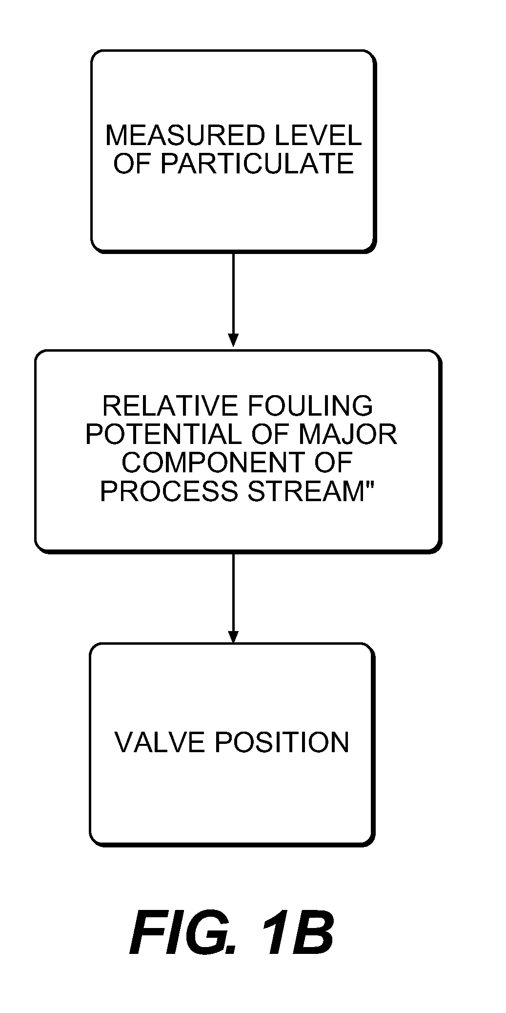
[0009]A method is provided for controlling fouling in a hydrocarbon refining process that includes measuring a level of particulate (e.g. the particulate concentration) in a process stream, including those streams in a hydrocarbon refining process, identifying an effective amount of additive capable of reducing particulate-induced fouling of process equipment in that stream based at least in part on the measured level of the particulate in the process stream, and, introducing and controlling the amount of additive to the hydrocarbon refining process to mitigate the fouling.
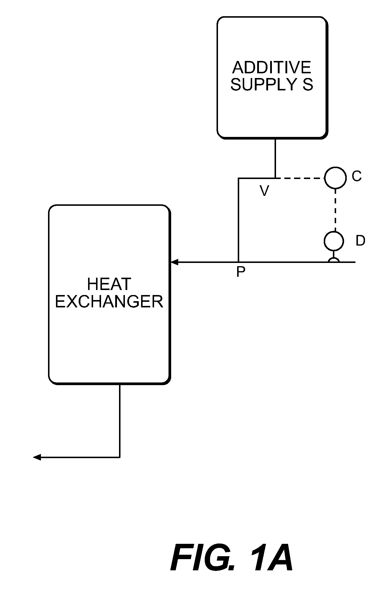
[0011]The present application also provides an additive control system for controlling fouling in a hydrocarbon refining system that includes a source of additive capable of reducing particulate-induced fouling in a hydrocarbon refining system, a valve to introduce to a process stream of the hydrocarbon refining system the additive capable of reducing particulate-induced fouling, a measuring device to measure a level of particulate in the process stream of the hydrocarbon refining system, and a controller to control an amount of additive introduced into the process stream via the valve based upon the level of particulate measured in the process stream. The additives are preferably introduced at a strategic location in the process unit to enhance the additive's effectiveness.

Problems solved by technology

Petroleum refineries incur additional energy costs, perhaps billions of dollars per year, due to fouling and the resulting attendant inefficiencies caused by the fouling.
More particularly, thermal processing of crude oils, blends and fractions in heat transfer equipment, such as heat exchangers, is hampered by the deposition of insoluble asphaltenes and other contaminants (i.e., particulates, salts, etc.).
Further, the asphaltenes and other organics are known to thermally degrade to coke when exposed to high heater tube surface temperatures.
For example, fouling in heat exchangers receiving petroleum-type process streams can result from a number of mechanisms including chemical reactions, corrosion, deposit of existing insoluble impurities in the stream, and deposit of materials rendered insoluble by the temperature difference (ΔT) between the process stream and the heat exchanger wall.
Further, the high ΔT inherent in a heat transfer operation results in high surface or skin temperatures when the process stream is introduced to the heater tube surfaces, which contributes to the precipitation of insoluble particulates.
Another common cause of fouling is attributable to the presence of salts, particulates and impurities (e.g. inorganic contaminants) found in the crude oil stream.
The buildup of insoluble deposits in heat transfer equipment creates an unwanted insulating effect and reduces heat transfer efficiency.
Fouling also reduces the cross-sectional area of process equipment, which decreases flow rates and desired pressure differentials and reduces process efficiency.
To overcome these disadvantages, heat transfer equipment must be taken offline and cleaned mechanically or chemically cleaned, resulting in lost production time.
The addition of additives, while of great utility and value for energy savings, does have attendant costs, including the cost of the additive itself and the cost of removing the additive from the process downstream.

Method used


Image

  • Method and system for controlling the amount of Anti-fouling additive for particulate-induced fouling mitigation in refining operations
  • Method and system for controlling the amount of Anti-fouling additive for particulate-induced fouling mitigation in refining operations
  • Method and system for controlling the amount of Anti-fouling additive for particulate-induced fouling mitigation in refining operations

Examples


example 1

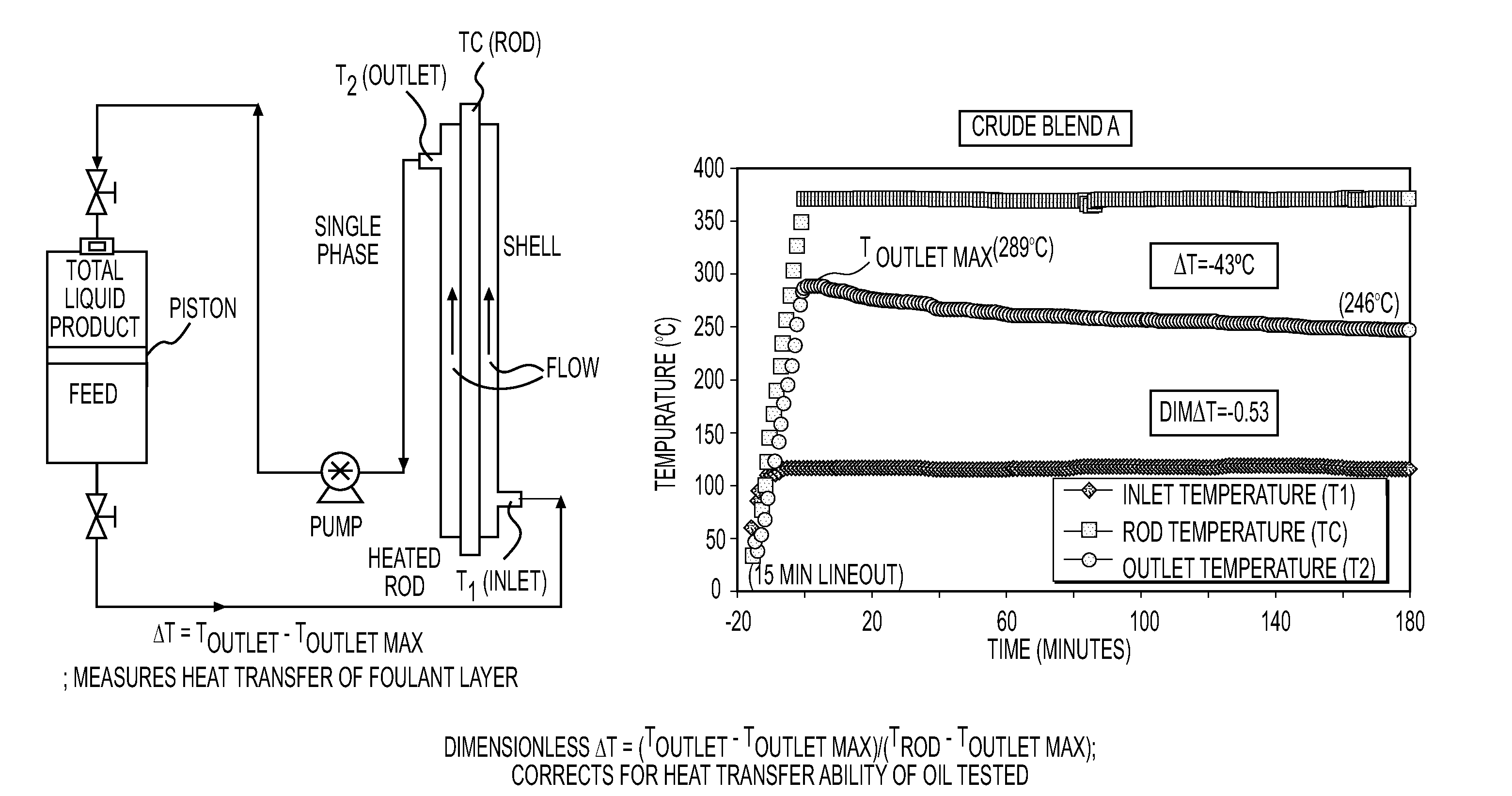
[0064]FIG. 2 shows the Alcor testing configuration used for measuring the relative fouling provided by a given crude oil in a simulated heat exchanger. The testing arrangement includes a reservoir containing a feed supply of crude oil. The feed supply is heated to a selected temperature (e.g. 150° C. / 302° F.). The housing shell contains a vertically oriented heated rod. The heated rod is typically formed from a carbon steel. The heated rod simulates a tube in a heat exchanger. The heated rod is electrically heated to a preset temperature (e.g. 370° C. / 698° F.) and maintained at such temperature during the trial. The feed supply is pumped across the heated rod at a constant flow rate (e.g. 3.0 mL / minute). The spent feed supply is collected in the top section of the reservoir. The spent feed supply is separated from the untreated feed supply oil by a sealed piston, thereby allowing for once-through operation. The system is pressurized with nitrogen (e.g. 400-500 psig) to ensure gases ...

example 2

[0066]During the constant surface temperature testing, foulant forms, deposits and builds up on the heated surface. The organic portion of the foulant deposits thermally degrade to coke. The coke deposits cause an insulating effect that reduces the efficiency and / or ability of the surface to heat the oil passing over it. The resulting reduction in outlet bulk fluid temperature continues over time as fouling continues. This reduction in temperature can be referred to as the outlet liquid ΔT or dT and can be dependent on the type of crude oil / blend, testing conditions and / or other effects, such as the presence of salts, sediment or other fouling promoting materials. Typically, the Alcor fouling test is carried out for 180 minutes. The total fouling, as measured by the total reduction in outlet liquid temperature is referred to as ΔT180 or dT180.

[0067]Alcor Dimensionless Delta T (DimΔT or Dim dT). The Alcor fouling test simulations provide a measurement of heat transfer resistance due ...


PUM

PropertyMeasurementUnit
foulingaaaaaaaaaa
fouling potentialaaaaaaaaaa
relative fouling potentialaaaaaaaaaa

Abstract

A method and system for controlling fouling in a hydrocarbon refining process that includes measuring a level of a particulate in a process stream of the hydrocarbon refining process in communication with a hydrocarbon refinery component, identifying an effective amount of additive capable of reducing particulate-induced fouling based at least in part on the measured level of the particulate in the process stream, and introducing the effective amount of additive to the hydrocarbon refining process.

Description

CROSS REFERENCE TO RELATED APPLICATION[0001]This application relates and claims priority to U.S. Provisional Patent Application No. 61 / 136,855, filed on Oct. 9, 2008 entitled “Method and System for Controlling the Amount of Anti-Fouling Additive for Particulate-Induced Fouling Mitigation in Refining Operations.”FIELD OF THE INVENTION[0002]The present invention relates to methods and systems of controlling the amount of anti-fouling additive to be introduced in an oil refining process.BACKGROUND OF THE INVENTION[0003]Petroleum refineries incur additional energy costs, perhaps billions of dollars per year, due to fouling and the resulting attendant inefficiencies caused by the fouling. More particularly, thermal processing of crude oils, blends and fractions in heat transfer equipment, such as heat exchangers, is hampered by the deposition of insoluble asphaltenes and other contaminants (i.e., particulates, salts, etc.). Further, the asphaltenes and other organics are known to thermal...

Claims


Application Information

Patent Timeline
Patent Type & Authority Applications(United States)
IPC IPC(8): C10G75/04C10G19/00G01N33/00
CPCC10G29/00C10G29/02C10G29/04C10G29/10C10G29/16C10G75/04C10G2300/1033C10G2300/4075C10G2300/80
Inventor WRIGHT, CHRIS ABRONS, GLEN B.ALVAREZ, MANUEL S.JACOBS, PETER W.FEILLER, SHARON A.LUTZ, GEORGE A.
Owner WRIGHT CHRIS A
Learn More