This helps you quickly interpret patents by identifying the three key elements:
Problems solved by technology
Method used
Benefits of technology
Benefits of technology
[0053]An advantage of some aspects of the invention is to provide a power circuit, for example, capable of preventing efficiency from being reduced by an increase in switching loss of a DC / DC converter (the DC / DC converter 15 in the example of FIG. 6) when a wideband envelope signal is received.
[0056]Thus, for example, when a wideband envelope signal is input, efficiency can be prevented from being reduced by an increase in the switching loss of the DC / DC converter.
[0060]Thus, for example, it is possible to realize the power circuit which allows the DC / DC converter to operate at an operation speed with high efficiency with respect to a Component around DC reaching about 90%.
[0066]Thus, for example, the power circuit which has high efficiency as a whole can be realized, and it is possible to realize the power circuit which allows the DC / DC converter to operate at an operation speed with high efficiency with respect to the component around DC reaching about 90%.
[0070]Thus, for example, when a wideband envelope signal is input, efficiency can be prevented from being reduced by an increase in the switching loss of the DC / DC converter.
[0076]As described above, according to the power circuit of the invention, for example, when a wideband envelope signal is input, efficiency can be prevented from being reduced by an increase in the switching loss of the DC / DC converter.
Problems solved by technology
The distortion compensation function includes a feed-forward compensation function, a pre-distortion compensation function or the like, but there is a limitation in the lowering of power consumption by only using the distortion compensation.
However, if the self-oscillating frequency is set to be high, since switching loss is increased or it exceeds a limit value of the switch device 32, the self-oscillating frequency is limited.
However, since a band of the communication system such as the WiMAX or the LTE is wide and a band of the envelope signal becomes wider, the AC component is limited.
However, in the wideband communication system such as the WiMAX or the LTE, since the envelope exists in a wide range, if the switching frequency of the DC / DC converter 15 is raised, switching loss is increased, so that the efficiency of the power circuit is reduced.
Consequently, the efficiency of the power circuit is reduced.
Method used
Image
Click on the blue label to locate the original text in one second.
Reading with bidirectional positioning of images and text.
Examples
embodiment 1
[0096]Hereinafter, Embodiment 1 of the invention will be described referring to the drawings.
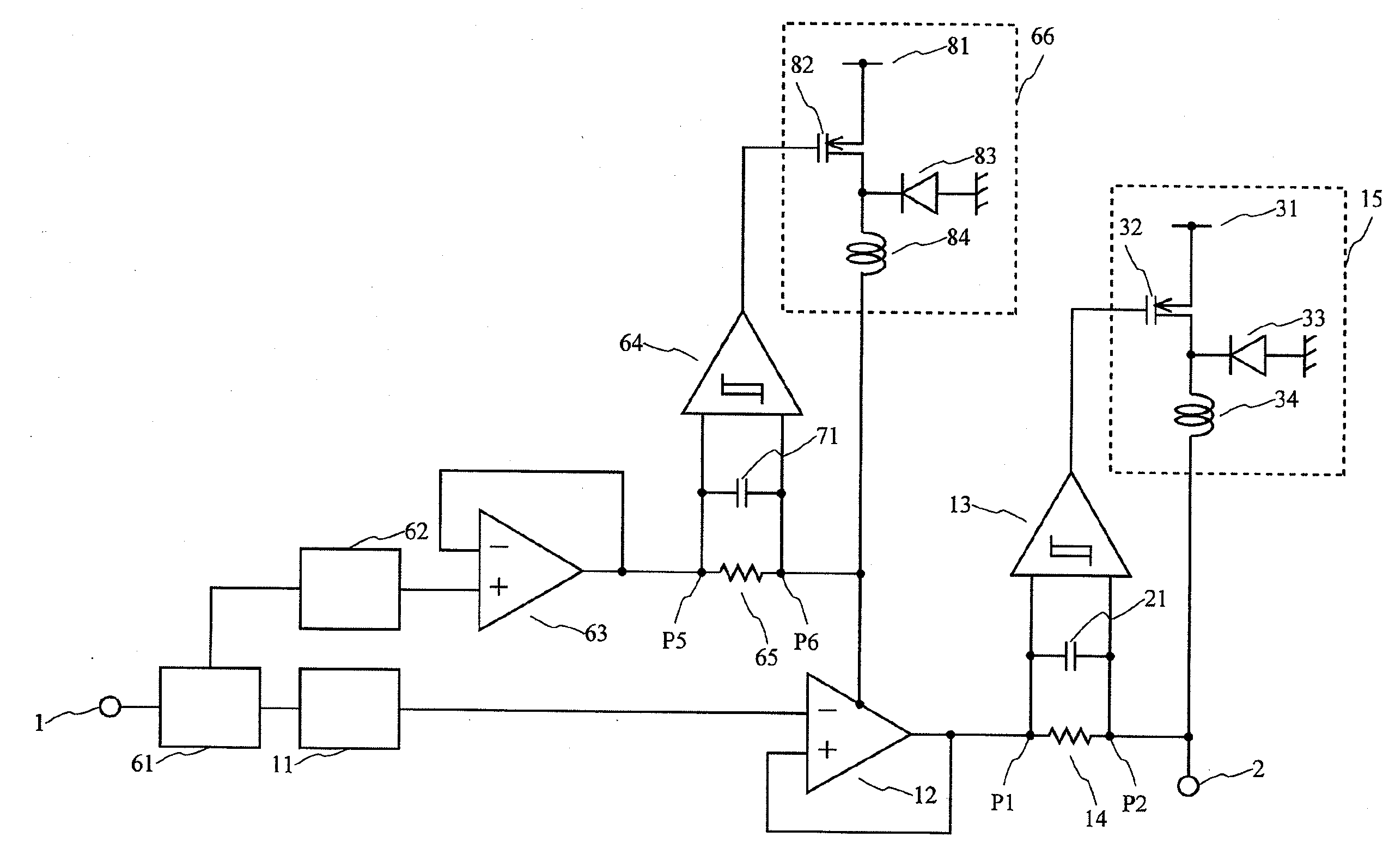
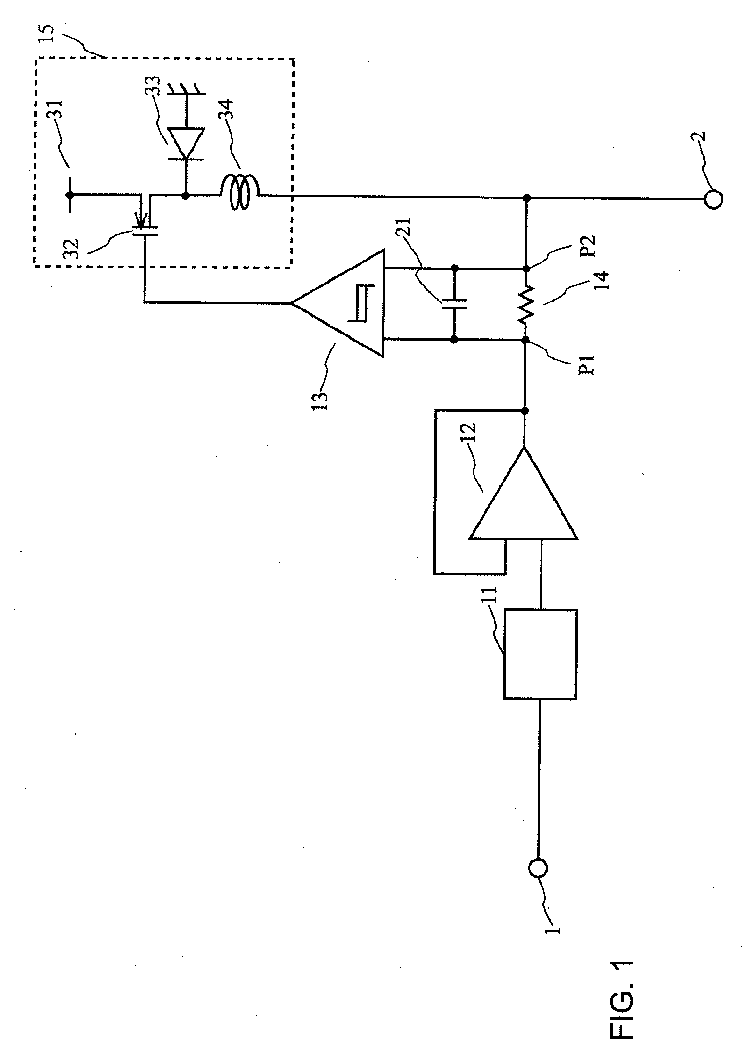
[0097]FIG. 1 is a circuit diagram showing a configuration example of an envelope amplifier (power circuit) according to one embodiment of the invention. For the purpose of convenience, the same reference numerals are used to designate the same elements as those shown in FIG. 6, and it does not unnecessarily limit the invention.
[0098]The envelope amplifier of the embodiment includes a waveform shaper 11, an OP amp 12, a hysteresiscomparator 13, a current detector 14, a capacitor 21 and a DC / DC converter 15, which are provided between an input terminal 1 and an output terminal 2.
[0099]The DC / DC converter 15 includes a supply voltage 31, a switch device 32, a diode 33 and an inductance 34.
[0100]Further, FIG. 1 shows nodes P1 and P2.
[0101]In detail, an input terminal of the waveform shaper 11 is connected to the input terminal 1, an output terminal of the waveform shaper 11 is connected to one ...
configuration example 1
[0148]The low pass filters (the capacitor 21, the low pass filter 43 and the capacitor 71 in the embodiment) are each inserted to input to the hysteresis comparators 13, 44 and 64 constituting the linear assist class BD amplifier, so that the operation frequency of the class D amplifier is suppressed.
[0149]In detail, in the embodiment, the linear assist class BD amplifier is used as a power source in which power used for the linear amplifier is changed based on the envelope information, the low pass filter is inserted after the current detection of the linear assist class ED amplifier so that information of a high frequency component is removed, and the operation frequency of the class D amplifier (the DC / DC converter) is restricted, so that the efficient power circuit can be realized (e.g., the configurations of FIGS. 1 to 3).
configuration example 2
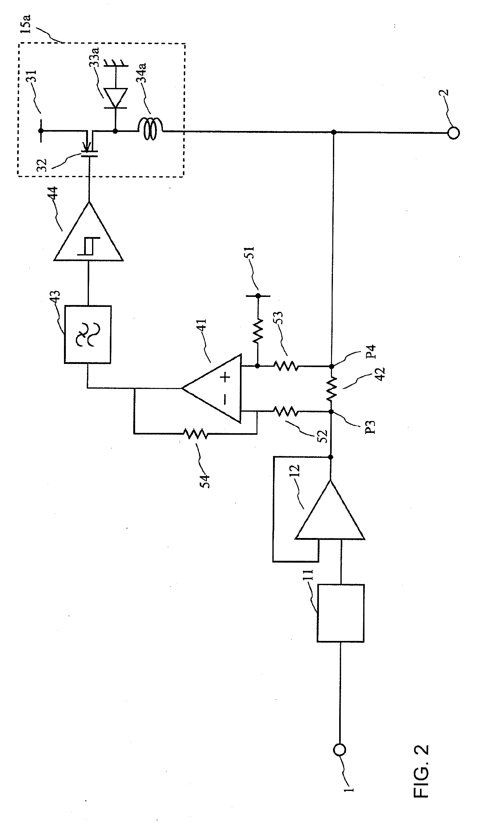
[0150]The linear assist class BD amplifier is applied to the linear amplifier (the OP amp 12 in the embodiment) constituting the linear assist class BD amplifier.
[0151]In detail, in the embodiment, the linear assist class ED amplifier is used as a power source in which power used for the linear amplifier is changed based on the envelope information, and the linear assist class BD amplifier is employed with respect to the power of the linear assist class BD amplifier (e.g., the configuration of FIG. 3).
BACKGROUND OF THE INVENTION[0001]1. Field of the Invention[0002]The present invention relates to a power circuit, for example, capable of preventing efficiency from being reduced by an increase in switching loss of a DC / DC converter when a wideband envelope signal is received.[0003]2. Description of Related Art[0004]According to the related art, when a radio frequencysignal such as a CDMA (Code Division Multiple Access) signal or a multi-carrier signal is power-amplified, a distortion compensation function is added to a common amplifier and an operation range of the common amplifier is expanded up to the vicinity of a saturation region, so that low power consumption is achieved. The distortion compensation function includes a feed-forward compensation function, a pre-distortion compensation function or the like, but there is a limitation in the lowering of power consumption by only using the distortion compensation. In this regard, in recent years, a method of achieving high effici...
Claims
Application Information
Patent Timeline
Application Date:The date an application was filed.
Publication Date:The date a patent or application was officially published.
First Publication Date:The earliest publication date of a patent with the same application number.
Issue Date:Publication date of the patent grant document.
PCT Entry Date:The Entry date of PCT National Phase.
Estimated Expiry Date:The statutory expiry date of a patent right according to the Patent Law, and it is the longest term of protection that the patent right can achieve without the termination of the patent right due to other reasons(Term extension factor has been taken into account ).
Invalid Date:Actual expiry date is based on effective date or publication date of legal transaction data of invalid patent.

