Toughened graphite electrodes for electric arc furnaces

a graphite electrode and electric arc furnace technology, applied in furnaces, other chemical processes, lighting and heating apparatus, etc., can solve the problems of inability to operate electrodes, significant downtime, loss of productivity, etc., to reduce the transverse and/or longitudinal coefficient of thermal expansion, improve strength, and less likely to fail

Inactive Publication Date: 2010-07-15
UT BATTELLE LLC
View PDF4 Cites 5 Cited by
  • Summary
  • Abstract
  • Description
  • Claims
  • Application Information

AI Technical Summary

Benefits of technology

[0011]In still another aspect, the invention is directed to a pitch binder composition and pitch binder-filler mix (e.g., a graphite electrode composition) in which carbon fibers are substantially homogeneously dispersed therein by application of the inventive method. In particular, the graphite electrode composition possesses improved properties of for example, increased strength and reduced transverse and / or longitudinal coefficient of thermal expansion.
[0012]Thus, as will be described in further detail below, the method advantageously provides graphite electrodes that are tougher and less likely to fail during EAF operations. The method improves existing methods for carbon fiber-reinforcement of graphite electrodes by homogeneously dispersing the carbon fibers throughout the electrode material. The method, therefore, in particular, permits smaller amounts of carbon fibers to be used per volume of graphitized electrode material, while advantageously lowering the cost of the electrode (and EAF process) and providing a graphite electrode of the same or greater overall toughness (i.e., strength or durability) than current carbon fiber-reinforced graphite electrodes.
[0013]In addition, by virtue of the increased toughness of the electrode, virtually all types of metal scrap can be processed by the arc furnace (i.e., for melting and reclamation) without requiring a pre-sorting step. Therefore, the method also provides the benefit of decreasing the processing time between EAF runs and increasing the output of processed metal.

Problems solved by technology

Cracking or failure of the electrode prior to complete melting of the scrap metal results in the inoperability of the electrode, which in turn causes significant downtime and loss of productivity as the furnace needs to be turned off, the scrap steel removed, and the faulty electrode replaced.
The pre-sorting of metal samples being sent to the arc furnace is a time consuming and costly process.
In addition, since the sorting process is generally highly susceptible to error in judgment, the sorting process also has a poor record in averting failure of electrodes.
However, a significant obstacle in the foregoing toughening method is that the carbon fibers are very expensive relative to the coke and pitch.
The significant expense of the carbon fibers results in the increased cost of the electrode, and therefore, an increased cost of the process.
Another problem in the carbon fiber toughening method is that the carbon fibers incorporated into the electrode mix are generally integrated into the mix as carbon fiber bundles (i.e., agglomerations) due to the very low dispersability of carbon fibers in pitch.
Therefore, the incorporation of agglomerated carbon fibers amounts to a highly inefficient and expensive method for toughening graphite electrodes.
In addition, the clumping of carbon fibers typically results in large sections of unreinforced electrode material, and thus, an electrode more prone to failure than an electrode containing carbon fibers homogeneously dispersed throughout the electrode material.

Method used


Image

  • Toughened graphite electrodes for electric arc furnaces
  • Toughened graphite electrodes for electric arc furnaces
  • Toughened graphite electrodes for electric arc furnaces

Examples


example 1

Preparation of Untreated Carbon Fibers / Pitch Samples

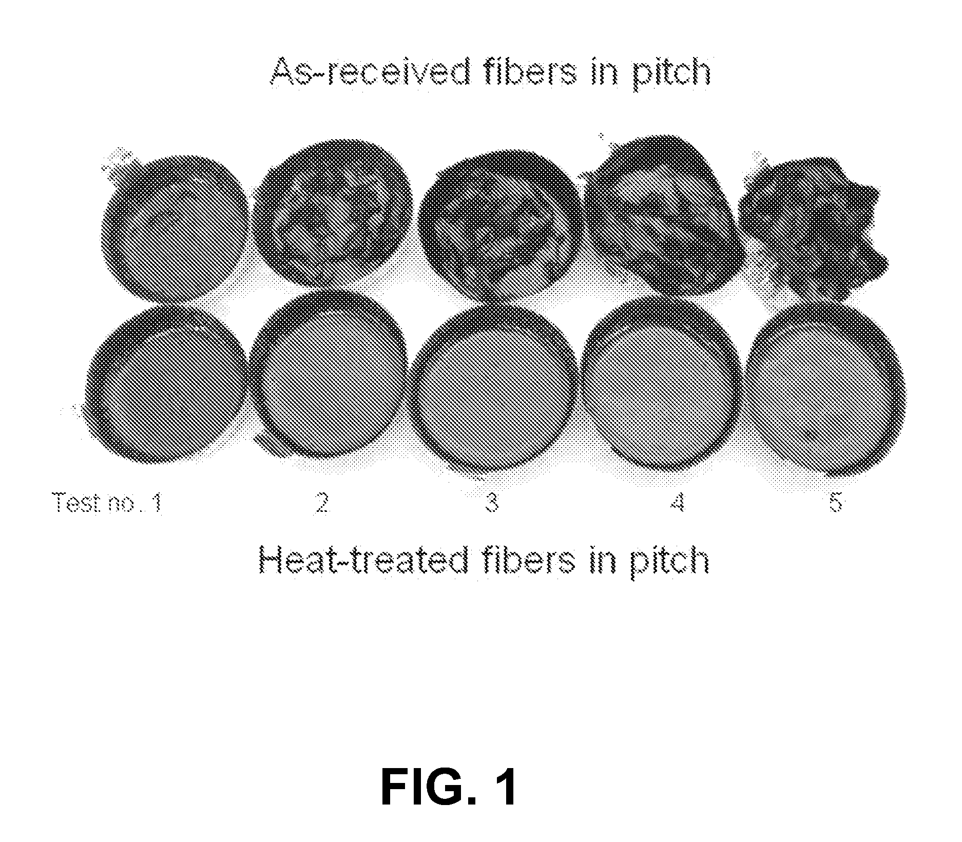
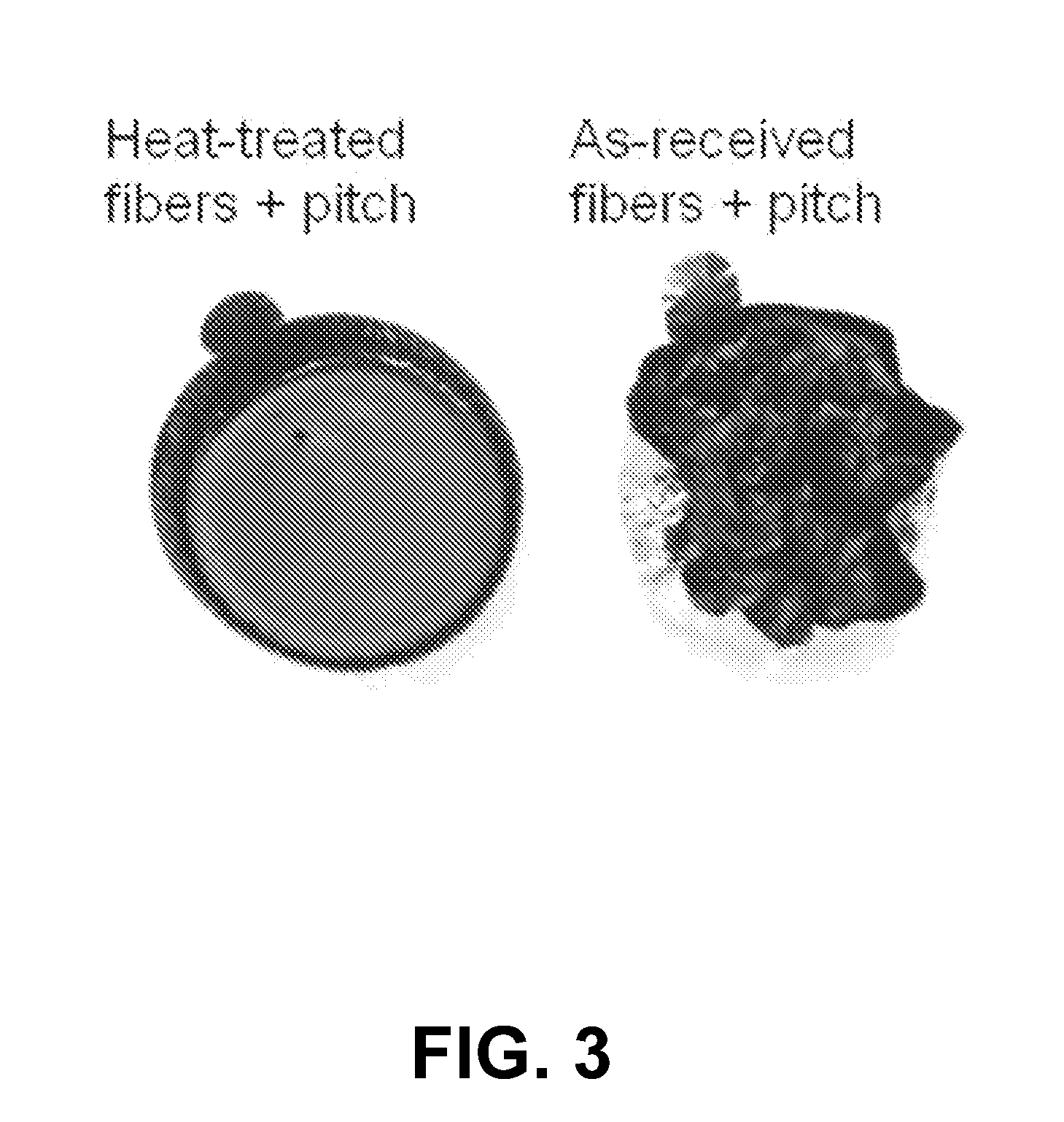
[0040]The dispersability of untreated carbon fibers in molten pitch was determined by mixing carbon fiber bundles, as-received without any surface treatment, into five samples of molten pitch as follows. First, five samples of coal-tar pitch were taken above their softening point and thereby made molten. Thereafter, a bundle of as-received fibers was added to each sample of molten pitch. The fiber-pitch mixture was stirred using a stainless steel spatula. Table 1 below lists the quantities of carbon fibers and pitch that were used for each of the five samples. The samples were made to vary in wt % of carbon fibers from 0.9 wt % to 6.3 wt % (for test nos. 1-5, respectively). The samples were then cooled to the solidification point of the pitch binder, after which the samples were analyzed.

TABLE 1Fiber and pitch quantities used for as-received fibersTest NumberQuantity of Fibers (g)Quantity of pitch (g)10.11813.19620.30713.56430.5071...

example 2

Heat Treatment of Carbon Fibers

[0041]Carbon fiber bundles were heat-treated by being heated to about 850° C. under flowing nitrogen and maintained at this temperature for one hour. The carbon fibers, thus treated, were cooled to below 200° C., after which point they could optionally be exposed to air without a detrimental effect. If exposed to air after the heat treatment, the carbon fibers were preferably used (e.g., combined with pitch) within two hours, and preferably less than one hour, after completion of the heat treatment. If maintained under a substantially inert atmosphere after the heat treatment, the carbon fibers may be stored in this manner until use.

example 3

Preparation of Heat-Treated Carbon Fibers / Pitch Samples

[0042]Heat-treated carbon fibers, prepared as described in Example 2, were then mixed into five pitch samples, and the resulting fiber-pitch mixtures solidified in a completely analogous manner as described above for the as-received carbon fibers in Example 1. Table 2 below lists the quantities of heat-treated carbon fibers and pitch that were used for the five samples. The five samples containing the heat-treated carbon fibers vary similarly in carbon fiber wt % to the five samples containing as-received carbon fibers. The five samples containing heat-treated carbon fibers were then solidified by cooling, and then analyzed, as described above for the as-received samples.

TABLE 2Fiber and pitch quantities used for heat-treated fibersTest NumberQuantity of Fibers (g)Quantity of pitch (g)10.10013.20320.30313.24330.50413.26140.70813.42650.90313.233


PUM

PropertyMeasurementUnit
viscosityaaaaaaaaaa
viscosityaaaaaaaaaa
temperatureaaaaaaaaaa

Abstract

The present invention is directed to a method for producing a carbon fiber-pitch binder composition, the method comprising combining surface-modified carbon fibers with a molten pitch binder such that the surface-modified carbon fibers are substantially homogeneously dispersed throughout said molten pitch binder, wherein said surface-modified carbon fibers possess a surface that has been modified in a manner that increases the dispersability of the carbon fibers into said molten pitch binder. The invention is also directed to a method for producing a toughened graphite electrode and a method for processing metal in an electric arc furnace. The invention is also directed to carbon fiber-pitch binder compositions prepared by the inventive method in which carbon fibers are substantially homogeneously dispersed in the composition.

Description

[0001]This invention was made with government support under Contract Number DE-AC05-00OR22725 between the United States Department of Energy and UT-Battelle, LLC. The U.S. Government has certain rights in this invention.FIELD OF THE INVENTION[0002]The present invention relates to the manufacture of pitch-containing materials, and more particularly the manufacture of graphite electrodes, especially those suited for use in electric arc furnaces.BACKGROUND OF THE INVENTION[0003]Graphite electrodes are used primarily in electric arc furnaces (EAF) to melt steel, titanium, and other metal scrap. The electrodes are consumed in the melting process. The graphite electrodes used for this purpose are typically cylindrical and can greatly vary in size. Graphite electrodes are typically manufactured by mixing petroleum coke particles with a pitch binder (typically coal-tar pitch), extruding the mix through a die, and subjecting the extruded mix to graphitizing conditions (e.g., temperatures of ...

Claims


Application Information

Patent Timeline
Patent Type & Authority Applications(United States)
IPC IPC(8): C21C5/52C09K3/00
CPCC21C5/5211C21C5/5229H01B1/04F27B3/085F27B3/20C21C5/5252Y02P10/20
Inventor PAPPANO, PETER J.CONTESCU, CRISTIAN I.
Owner UT BATTELLE LLC
Why Eureka
Try Eureka