
Barrier stent and use thereof

a stent and barrier technology, applied in the field of new stent construction, can solve the problems of stent restenosis, increase neointima formation, restenosis rate by about 10%, etc., and achieve the effects of promoting re-endothelialization, high aspect ratio, and preferential penetration

Inactive Publication Date: 2010-07-15
UNIV OF TENNESSEE RES FOUND
View PDF2 Cites 22 Cited by
  • Summary
  • Abstract
  • Description
  • Claims
  • Application Information

AI Technical Summary

Benefits of technology

"The present invention relates to a vascular stent with a unique outer coating that includes pores that are substantially impermeable to vascular smooth muscle cell migration. The stent also includes a first polymeric layer that promotes re-endothelialization and inhibits thrombosis, and a second polymeric layer that is porous but impermeable to cells. The stent can be used to prevent neointimal hyperplasia, in-stent thrombosis, and other vascular bed diseases. The stent also has drug delivery capabilities and can maintain the benefits of current drug-coated stents."

Problems solved by technology

Although, the conventional endovascular stents are able to block elastic recoil and vascular negative remodeling, resulting in the reduction of the restenosis rate by about 10%, they cannot inhibit neointima thickening, and may even increase neointima formation which results in in-stent restenosis (Bennett, Heart 89(2):218-224 (2003); Holmes, Jr., Rev. Cardiovasc. Med. 2(3):115-119 (2001); Lowe et al., J. Am. Coll. Cardiol.
However, after angioplasty and stent implantation, the endothelial cells are damaged and / or denuded.
2(4):316-325 (2000); Bittl et al., Am. J. Cardiology 70:1533-1539 (1992)), but intravascular brachytherapy has two undesirable consequences: an increase in the risk of thrombosis and stimulation of hyperplasia at the ends of the stent (the candy wrapper effect).
The early intriguing success of these interventions, however, has exposed a potential liability of an indiscriminate antiproliferative approach for restenosis prevention.
7(5):651-656 (1996); Yuan et al., J. Endovasc. Surg. 5(4):349-358 (1998)), but these coatings did not provide for endothelial cell migration, nor were they utilized in combination with other materials.

Method used


Image

  • Barrier stent and use thereof
  • Barrier stent and use thereof
  • Barrier stent and use thereof

Examples


example 1

Comparison of Conventional Stent to Stent Having Outer Polyethylene Layer Impermeable to Cells

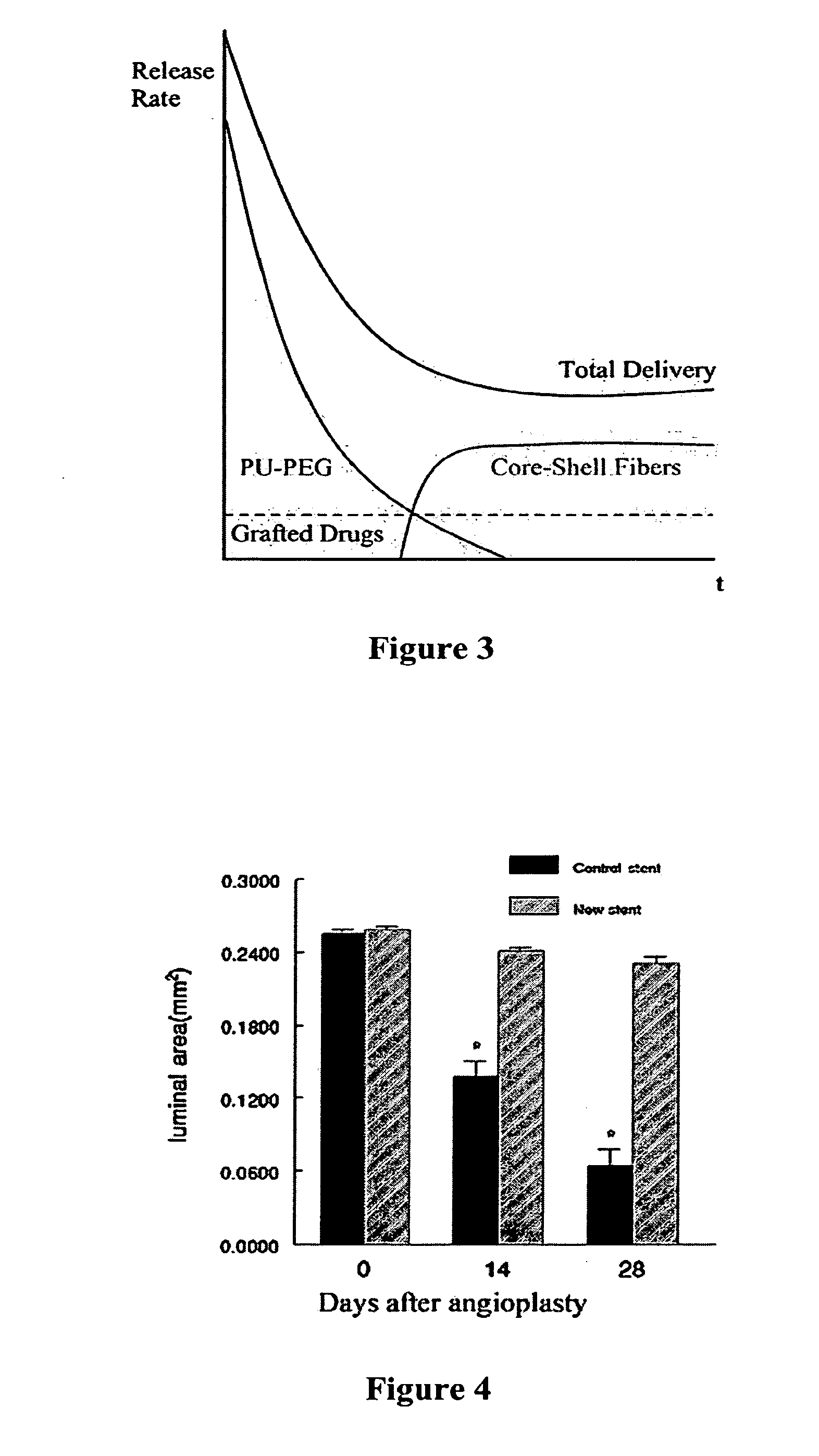
[0075]Prototype barrier stents were prepared by Scientific Commodity, Inc., at the request of the inventors using an outer polyethylene layer that is impermeable to all cells. These prototype stents were compared in vivo to conventional mesh stents.

[0076]Rat carotid artery balloon angioplasty was performed as described in our previous study (Hamuro et al., J. Vasc. Interv. Radiol. 12(5):607-611 (2001), which is hereby incorporated by reference in its entirety). Immediately after angioplasty, the stents were implanted into the injured carotid arteries. The animals were sacrificed immediately after (0 day) and at 14 and 28 days after stent implantation, and the stented segments were isolated for histological analysis. As shown in FIG. 4, the luminal areas in carotid arteries with the prototype (new) stents are greater that those with conventional stents. These results suggest that use of a ce...

example 2

Synthesis and Evaluation of Outer Coating Materials

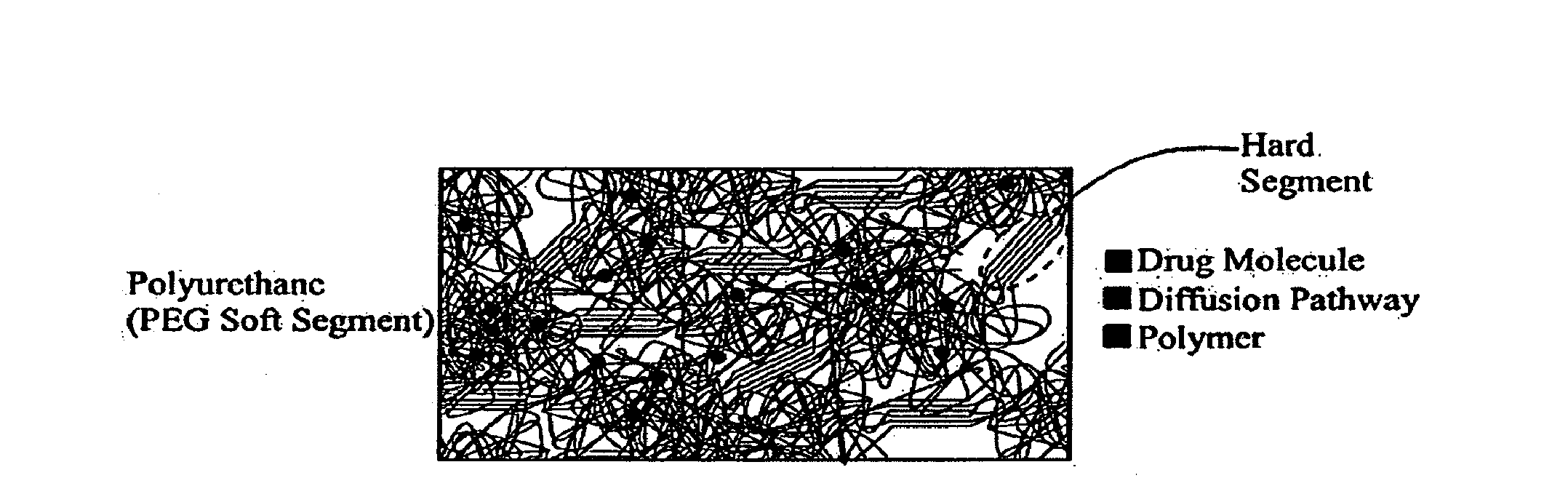
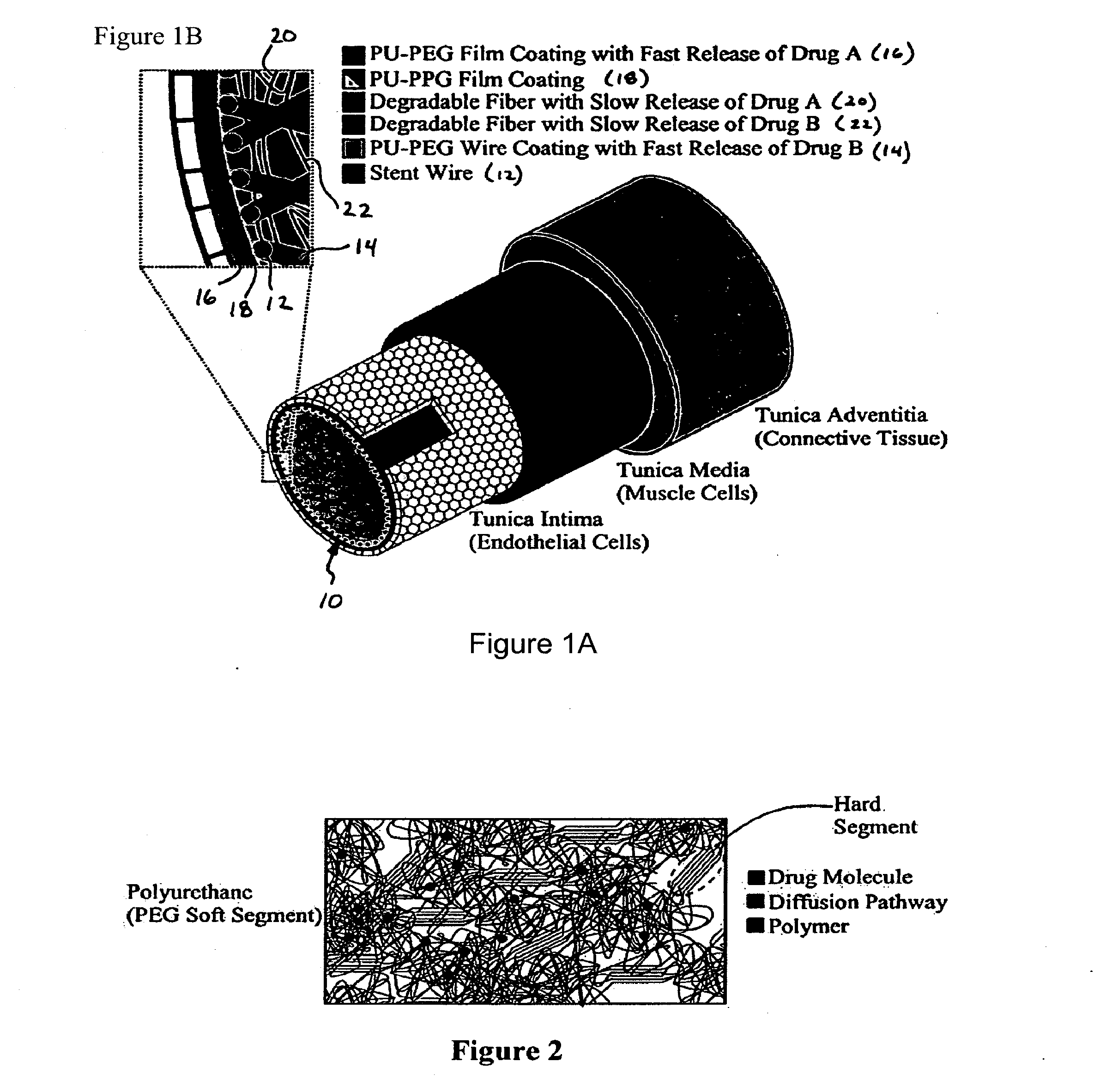
[0081]The selection of polyurethanes for outer stent coatings is based on biocompatibility (Brown, J. Intraveneous Nursing 18:120-122 (1995); Szycher et al., Medical Devices Technol. 3:42-51 (1992); Jeschke et al., J. Vascular Srg. 29:168-176 (1999), each of which is hereby incorporated by reference in its entirety).

[0082]Polyurethanes are polymers consisting of hard and soft segments within the molecular chain. The morphology of polyurethane is characterized by the aggregation of hard segments, rigid domains, dispersed in a matrix of the soft segments. The phase separation is due to the chemical differences between the hard and soft segments. The polyurethane chemistry permits tailoring of properties to meet numerous applications through the appropriate selection of the reactive intermediates: diisocyanates, soft segment, and chain coupler. Polyurethane elastomers exhibit elastic behavior under low stress conditions. The more elast...

example 3

Prospective Example 3

Synthesis and Evaluation of Mixed Fiber / Film Coating Materials

[0096]A composite fibrous polyurethane material using appropriate layers of continuous filament microfibers, nonwoven webs of microfibers, and nonwoven webs of nanofibers will be synthesized. Continuous filaments will be produced using micro-extrusion melt spinning (MS) techniques, nonwoven webs made of microfibers will be produced using melt blowing (MB), and nonwoven webs made of nanofibers will be produced using electrospinning (ES). The polyurethanes that will be used in ES do not need to be melt processable since the polymer is dissolved in solvent.

[0097]Continuous filaments of PU will be produced first using a micro-extruder with an air quench, drawing and continuous take-up system (e.g., Randcastle Microtruder Model No. RCPR with a ⅝-inch diameter screw, single spinneret die, two godets for drawing the extruded filaments). Extruded filaments will be unwound and tested for biocompatibility, degr...


PUM

PropertyMeasurementUnit
widthaaaaaaaaaa
widthaaaaaaaaaa
pore aspect ratioaaaaaaaaaa

Abstract

The present invention relates to a vascular stent that includes an expandable stent defining an interior compartment, a first polymeric layer exposed to the interior compartment defined by the stent, the first layer comprising an agent that promotes re-endothelialization, an agent that inhibits thrombosis, or a combination thereof, and a second polymeric layer at least partially external of the stent, the second layer being adapted for contacting a vascular surface and being characterized by pores that are substantially impermeable to vascular smooth muscle cell migration. Method of making and using the vascular stent are also disclosed.

Description

[0001]This application claims the benefit of U.S. Provisional Patent Application Ser. No. 60 / 659,899, filed Mar. 9, 2005, which is hereby incorporated by reference in its entirety.FIELD OF THE INVENTION[0002]The present invention relates generally to a novel stent construction; use thereof to prevent thrombosis and neointima formation, and thereby treat coronary or vascular diseases; as well as methods of manufacture.BACKGROUND OF THE INVENTION[0003]More than 1.5 million patients receive percutaneous transluminal coronary angioplasty (“PTCA”) and peripheral artery angioplasty (“PTA”) every year in the world. Despite being successful procedures, PTCA and PTA remain limited by restenosis that occurs in 30-60% of patients (Rajagopal et al., Am. J. Med. 115:547-553 (2003)). Thus, restenosis after angioplasty is not only important clinically but also for its impact on health-care costs.[0004]The pathological mechanisms of restenosis are neointimal formation, elastic recoil, and vascular ...

Claims


Application Information

Patent Timeline
Patent Type & Authority Applications(United States)
IPC IPC(8): A61F2/06B05D7/00
CPCA61L31/10A61L31/146A61L31/16A61L2300/412A61L2420/08A61L2300/45A61L2300/608D01D5/0015A61L2300/42
Inventor JENNINGS, LISA K.ZHANG, CHUNXIANGWADSWORTH, LARRY C.BRESEE, RANDALL R.BENSON, ROBERTO S.STEPHENS, CHRISTOPHER P.
Owner UNIV OF TENNESSEE RES FOUND
Learn More