Extreme ultraviolet light source apparatus

a light source and ultraviolet light technology, applied in the field of extreme ultraviolet (euv) light source apparatus, can solve the problems of reducing the reflectance, damaging the optical elements, and scattered debris damage the optical elements within the chamber, and achieves the effect of efficient collection, high efficiency, and efficient captur

Active Publication Date: 2010-07-22
GIGAPHOTON
View PDF7 Cites 134 Cited by
  • Summary
  • Abstract
  • Description
  • Claims
  • Application Information

AI Technical Summary

Benefits of technology

[0019]According to the one aspect of the present invention, by using the ionization laser unit for irradiating the neutral particles with the ionization laser beam to convert the neutral particles into ions, the neutral particles included in debris can be ionized with high efficiency, and therefore, not only the charged particles but also the neutral particles included in debris can efficiently be trapped by the magnetic field or the electric field formed within the chamber. Accordingly, the debris can efficiently be collected, and optical elements such as the collector mirror within the chamber can be protected from the debris da

Problems solved by technology

The melted solid material becomes debris having diameters of several micrometers or more and is emitted in a large amount, and damages optical elements within a chamber such as an EUV collector mirror coated with a mirror coating and reduces its reflectance.
Further, in the case where a liquid material is used as the target, scattered debris also damages the optical elements within the chamber.
However, when tin is used as the target, the debris of tin scattered by the laser irradiation adheres to the EUV collector mirror, and the reflectance of the EUV light is reduced and the lifetime of the EUV collector mirror becomes shorter.
If the technology is applied to an EUV light source apparatus, it is impossible to prevent the mirror damage (damage due to sputtering or adherence of debris).
Fur

Method used


Image

  • Extreme ultraviolet light source apparatus
  • Extreme ultraviolet light source apparatus
  • Extreme ultraviolet light source apparatus

Examples


embodiment 1

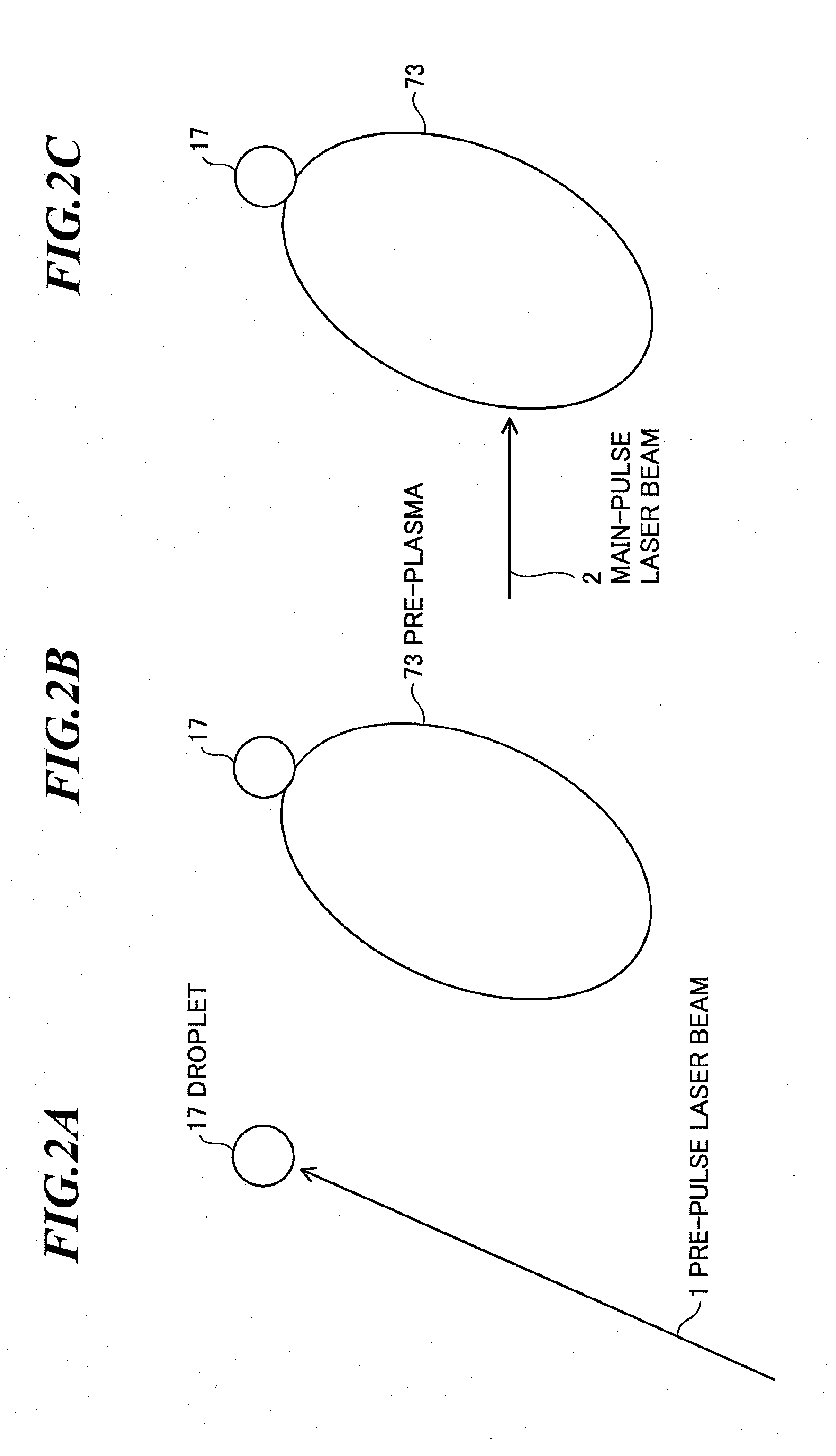
[0071]The first embodiment is an embodiment in a pre-pulse system (e.g., a pre-plasma system or a mass-limited target system) for expanding a target by using a pre-pulse laser beam, and then, irradiating the expanded target with a main-pulse laser beam.

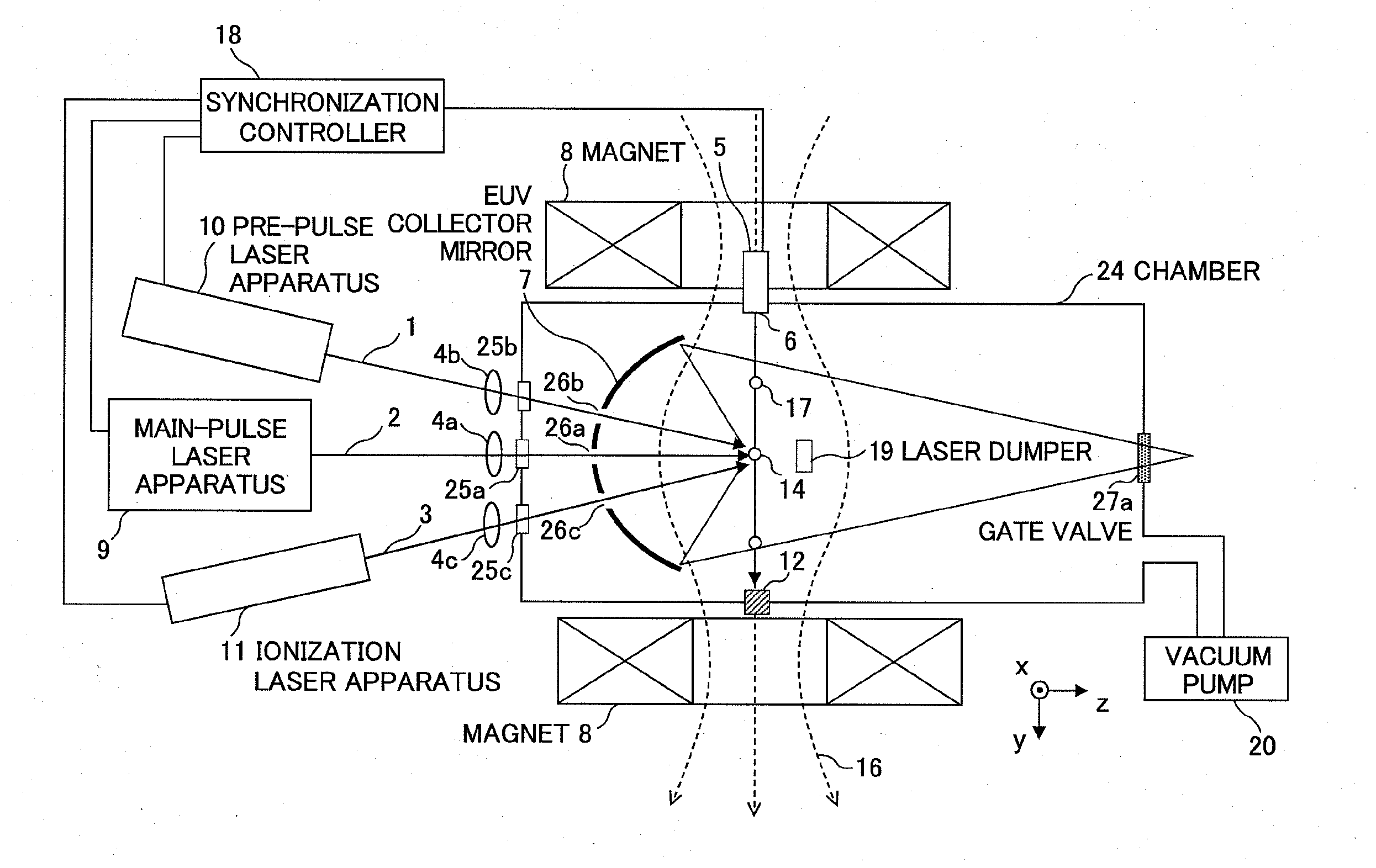
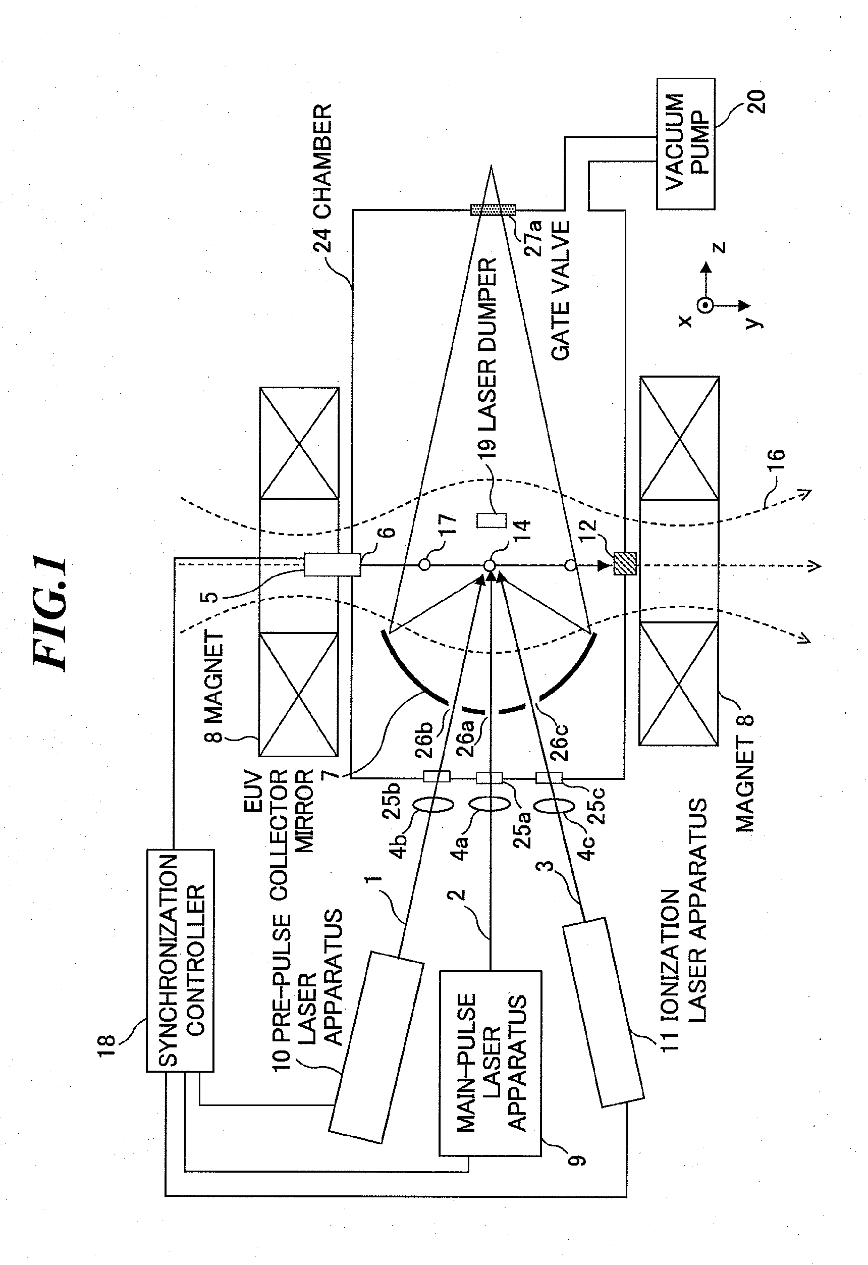
[0072]First, referring to FIG. 1, a basic configuration of an extreme ultraviolet (EUV) light source apparatus will be explained. FIG. 1 is a schematic diagram showing a configuration of an EUV light source apparatus according to the first embodiment of the present invention. The EUV light source apparatus employs a laser produced plasma (LPP) system for generating EUV light by irradiating a target with a laser beam to excite the target.

[0073]The EUV light source apparatus according to the first embodiment as shown in FIG. 1 includes a target supply unit 5, a main-pulse laser apparatus (a plasma generation laser unit for turning a target material into plasma) 9, a pre-pulse laser apparatus 10, an ionization laser apparatus (an ionizat...

embodiment 2

[0126]FIG. 8 is a schematic diagram showing a configuration of an EUV light source apparatus according to the second embodiment of the present invention, and FIG. 9 is a schematic diagram showing the EUV light source apparatus according to the embodiment seen from an output side of EUV light in a direction toward a light emission point.

[0127]As shown in FIG. 8, in the embodiment, the space near the plasma emission point 14 between the EUV collector mirror 7 and the plasma emission point 14 is irradiated with the ionization laser beam 3 as a sheet-shaped beam radiated in a direction orthogonal to the plain of paper of the drawing, and thereby, neutral particles moving toward the EUV collector mirror 7 are ionized to protect the EUV collector mirror 7. The sheet-shaped beam is created of a laser beam multiple-reflected as shown in FIGS. 10A and 10B, or a laser beam may be expanded to have a sheet shape by using a beam expander.

[0128]Further, as a mechanism of introducing the ionizatio...

embodiment 3

[0133]FIG. 11 is a schematic diagram showing a configuration of an EUV light source apparatus according to the third embodiment of the present invention, and FIGS. 12A and 12B show a relationship between a concave mirror and an ionization laser beam in the third embodiment.

[0134]As shown in FIG. 11, in the embodiment, a pair of concave mirrors 32 for multiple-reflecting an ionization laser beam is provided. As shown in FIGS. 12A and 12B, the pair of concave mirrors 32 are provided substantially symmetrically with respect to a line connecting the plasma emission point 14 and the center of the EUV collector mirror 7. The ionization laser beam 3 from the ionization laser apparatus (outside of the drawing) enters, for example, the rear surface of one concave mirror 32 from a direction as shown by an arrow in FIG. 12A. The ionization laser beam 3 is multiple-reflected between the pair of concave mirrors 32 and forms a conical beam, applied to a space near the plasma emission point 14 bet...


PUM


Abstract

In an EUV light source apparatus, a collector mirror is protected from debris damaging a mirror coating. The EUV light source apparatus includes: a chamber in which extreme ultraviolet light is generated; a target supply unit for supplying a target material into the chamber; a plasma generation laser unit for irradiating the target material within the chamber with a plasma generation laser beam to generate plasma; an ionization laser unit for irradiating neutral particles produced at plasma generation with an ionization laser beam to convert the neutral particles into ions; a collector mirror for collecting the extreme ultraviolet light radiated from the plasma; and a magnetic field or electric field forming unit for forming a magnetic field or an electric field within the chamber so as to trap the ions.

Description

CROSS-REFERENCE TO RELATED APPLICATION[0001]The present application claims priority from Japanese Patent Applications No. 2008-319161 filed on Dec. 16, 2008 and No. 2009-211684 filed on Sep. 14, 2009, the contents of which are incorporated herein by reference in their entirety.BACKGROUND OF THE INVENTION[0002]1. Field of the Invention[0003]The present invention relates to an extreme ultraviolet (EUV) light source apparatus for generating extreme ultraviolet light by irradiating a target material with a laser beam.[0004]2. Description of a Related Art[0005]In recent years, as semiconductor processes become finer, photolithography has been making rapid progress toward finer fabrication. In the next generation, microfabrication at 60 nm to 40 nm, further, microfabrication at 30 nm and beyond will be required. Accordingly, in order to fulfill the requirement for microfabrication at 30 nm and beyond, for example, exposure equipment is expected to be developed by combining an EUV light so...

Claims


Application Information

Patent Timeline
IPC IPC(8): G21K5/02
CPCG03F7/70033G03F7/70916H05G2/005H05G2/008H05G2/003
Inventor YANAGIDA, TATSUYAENDO, AKIRAKOMORI, HIROSHINAGAI, SHINJIKAKIZAKI, KOUJIABE, TAMOTSUHOSHINO, HIDEO
Owner GIGAPHOTON
Why Eureka
Try Eureka