
Laser source device and laser processing device

a laser source and laser processing technology, applied in lasers, manufacturing tools, welding/soldering/cutting articles, etc., can solve problems such as the quality of processing may deteriora

Inactive Publication Date: 2010-07-22
ORMON CORP
View PDF3 Cites 27 Cited by
  • Summary
  • Abstract
  • Description
  • Claims
  • Application Information

AI Technical Summary

Benefits of technology

[0006]A laser source device is proposed, including a resonator for generating a laser beam and an amplifier for amplifying the laser beam from the resonator in order to emit a laser beam having a high peak power. The amplifier adopts the MOPA (Master Oscillator and Power Amplifier) method, which is capable of emitting a beam having a high peak power by amplifying, for example a weak laser beam as a seed light.

Problems solved by technology

As a result, there is a possibility that the quality of processing may deteriorate.

Method used


Image

  • Laser source device and laser processing device
  • Laser source device and laser processing device
  • Laser source device and laser processing device

Examples


Embodiment Construction

[0031]Hereinafter, the embodiments of the invention are described in detail with reference to the drawings. The same symbols are applied to the same and the corresponding parts in the drawings and are not repeatedly described.

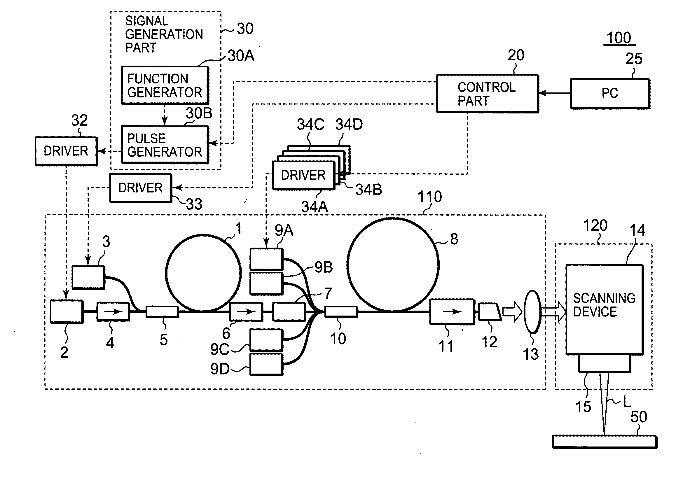
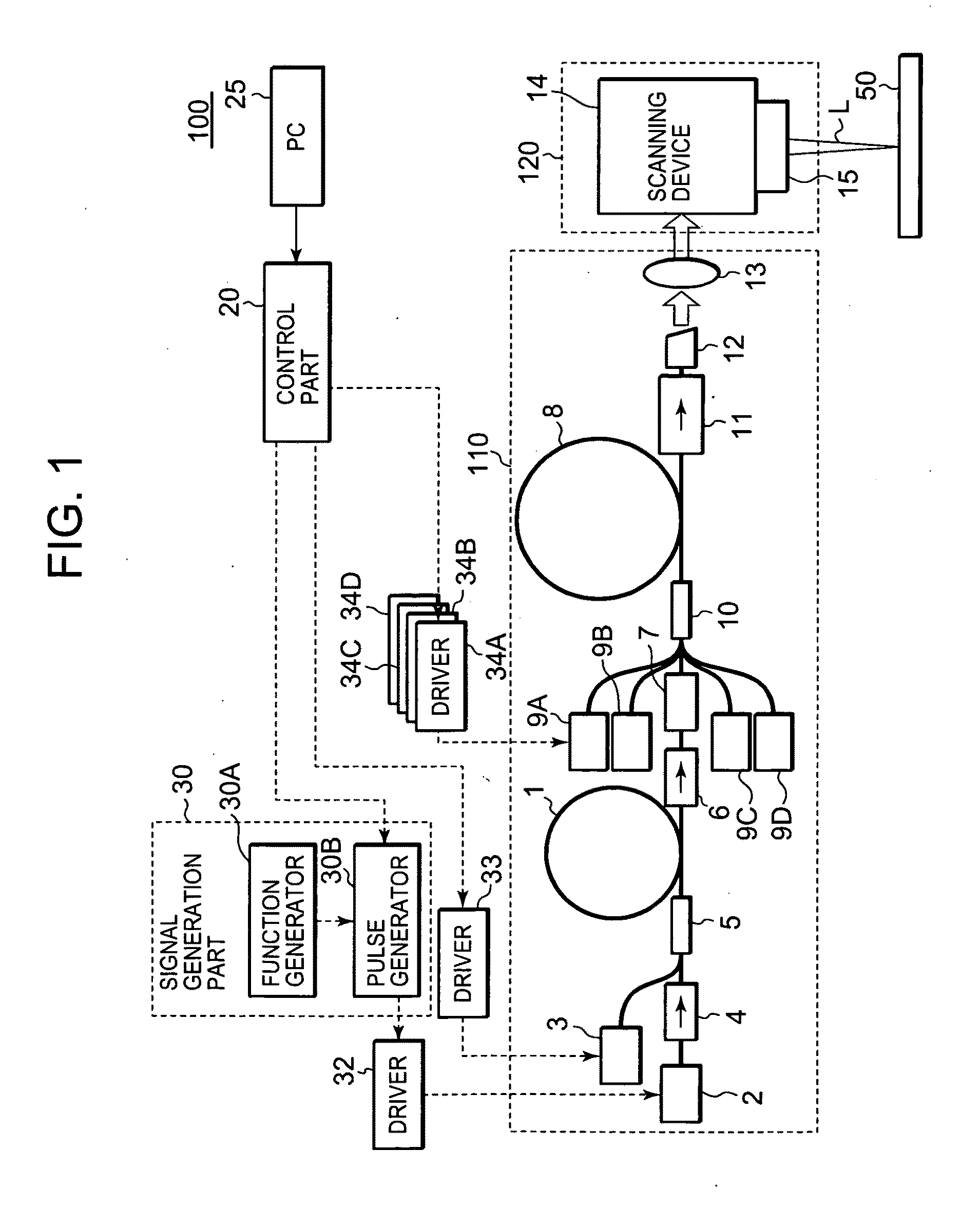
[0032]FIG. 1 is a view showing a structure of a laser source device and a laser processing device equipped with the laser source device according to the embodiment. The laser processing device 100 has a laser source device 110 and a laser emission device 120 with reference to FIG. 1.

[0033]The laser source device 110 has an optical fiber 1, laser diodes 2, 3, isolators 4, 6, and a coupler 5.

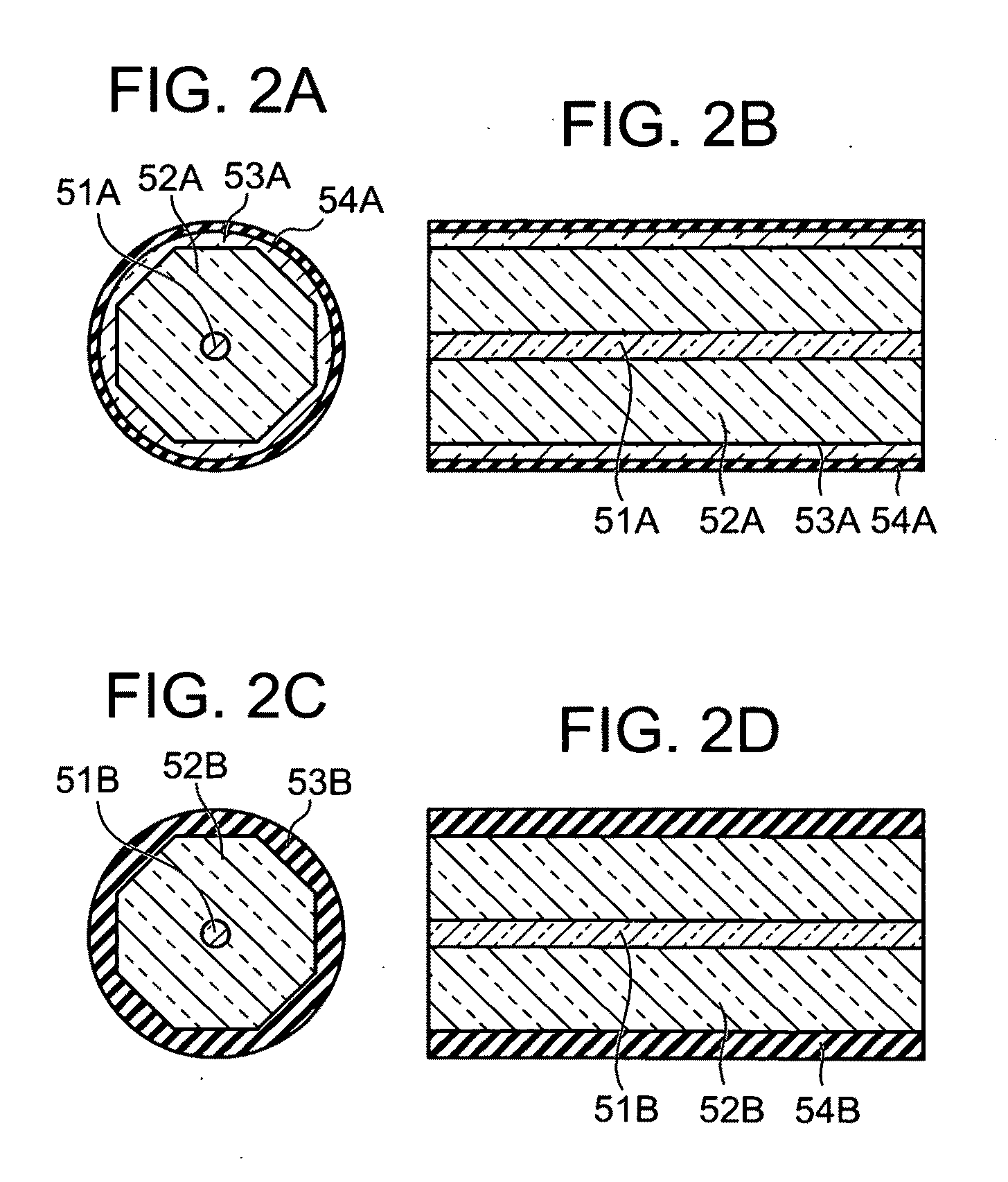
[0034]The optical fiber 1 has a core doped by a rare-earth element, being an optical amplifying content. The types of the rare-earth element are for example Er (erbium), Yb (ytterbium), are Nd (neodymium), but not limited to these elements. The rare-earth element doped in the core is Yb (ytterbium) according to the embodiment.

[0035]Generally, an optical fiber has a clad aroun...


PUM

PropertyMeasurementUnit
Poweraaaaaaaaaa
Wavelengthaaaaaaaaaa

Abstract

A laser source device includes an optical amplifier having an optical amplifying medium that is configured to amplify a seed beam when the seed beam and an exciting beam are entered, a seed beam source for emitting a laser beam as the seed beam, and an exciting beam source for emitting an exciting beam. The seed beam source emits a pulse beam as the seed beam during a predetermined principal irradiation period. The seed beam source emits a substantially continuous beam as the seed beam, having a smaller power than a peak power of the pulse beam during a supplemental irradiation period different from the principal irradiation period. The exciting beam source emits the exciting beam such that the power of the exciting beam is smaller during the supplemental irradiation period than the power of the exciting beam during the principal irradiation period.

Description

BACKGROUND[0001]The invention is related to a laser source device and a laser processing device including the laser source device.[0002]A typical laser process such as laser marking, laser drilling or laser welding requires a laser device capable of emitting a laser beam having a high peak power.[0003]Processing devices having a solid-state laser resonator including Nd-YAG (Yttrium Aluminum Garnet) or Nd—YVO4 crystal as a laser source are traditionally known. These processing devices generally employ a Q-switch element for emitting a laser beam pulse having a high peak power.[0004]A typical example of the Q-switch is an AOQ-switch using an acousto-optic element. This Q-switch element is made by applying RF signals (high frequency signals) to an AO element represented by a fused quartz to induce Bragg diffraction inside the element. A resonator is configured such that a laser resonance occurs while diffraction is induced; thereby a photo-switch using diffraction is configured.[0005]I...

Claims


Application Information

Patent Timeline
IPC IPC(8): H01S3/10B23K26/00H01S3/00H01S3/23
CPCH01S3/06754H01S3/10015H01S3/2316B23K26/40B23K2103/50B23K26/0622B23K26/382B23K26/22B23K2103/42B23K26/082
Inventor ISHIZU, YUICHINAKANO, FUMIHIKONISHIMURA, MITSURU
Owner ORMON CORP
Learn More