
Ion-permeable diaphragm

Inactive Publication Date: 2010-07-29
KURITA WATER INDUSTRIES LTD
View PDF1 Cites 2 Cited by
  • Summary
  • Abstract
  • Description
  • Claims
  • Application Information

AI Technical Summary

Benefits of technology

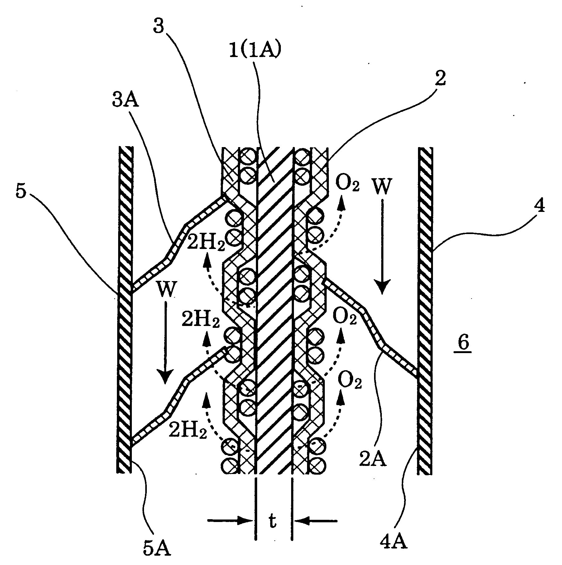
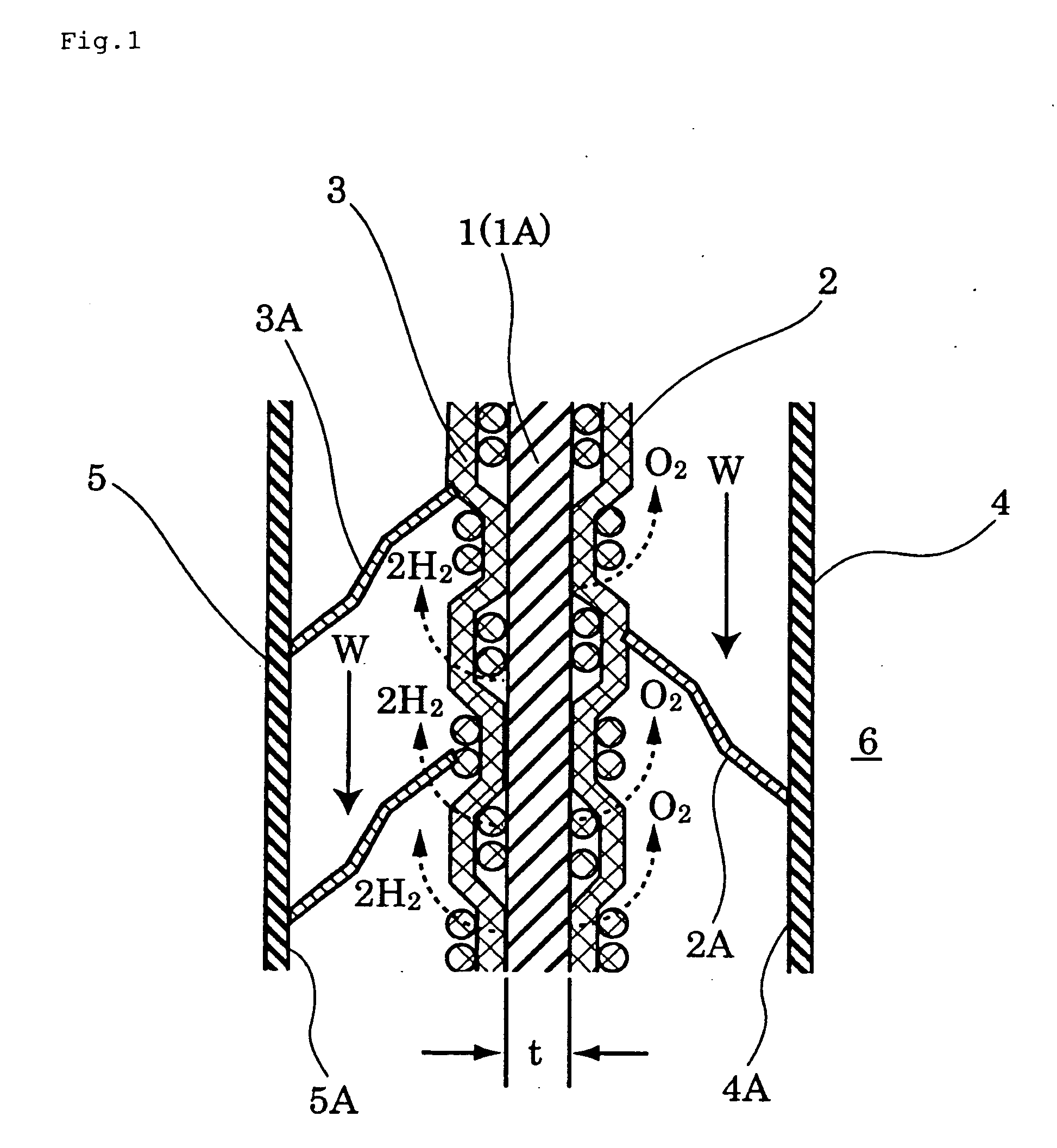
[0019]According to the above invention (Invention 1), the ions in alkaline water electrolysis can pass quickly through the ion-permeable diaphragm having enhanced hydrophilicity, which allows reducing the electric resistance of the diaphragm itself. Moreover, the porous structure of the ion-permeable diaphragm is dense, such that gas bubbles cannot pass through the pores. As a result, the oxygen and the like generated on the anode side does not become mixed with the hydrogen generated on the cathode side of the ion-permeable diaphragm, which allows thus keeping high the purity of the hydrogen gas.
[0021]According to the above inventions (Inventions 2 to 5), the membrane material itself exhibits extremely good hydrophilicity and excellent ion conductivity, and hence the ion-permeable diaphragm can be ideally used as a diaphragm for alkaline water electrolysis devices.
[0022]In the above inventions (Inventions 1 to 5), preferably, the thickness of the membrane material is 100 μm or greater (Invention 6). A thicker membrane material allows ensuring a desired membrane strength, but may entail an increase in the electric resistance of the membrane. According to the above invention (Invention 6), however, the membrane material exhibits extremely good hydrophilicity and excellent ion conductivity, so that a desired membrane strength can be ensured without increases in the electric resistance of the membrane, even if the membrane material is somewhat thick.
[0023]In the ion-permeable diaphragm of the present invention, thus, the ions in alkaline water electrolysis can pass quickly through the ion-permeable diaphragm having enhanced hydrophilicity. This allows reducing the electric resistance of the membrane, which in turn allows reducing power consumption in the alkaline water electrolysis device, while enhancing the electrolysis efficiency of the latter. Moreover, the oxygen and the like generated on the anode side does not become mixed with the hydrogen generated on the cathode side of the ion-permeable membrane, which allows allaying concerns relating to impaired hydrogen manufacturing efficiency.

Problems solved by technology

The former method involves complex operations and requires extremely large facilities, and is thus problematic in terms of initial cost.
This results in greater electric resistance and worse electrolysis efficiency, which is problematic.
Asbestos yarn corrodes at temperatures of 100° C. or above, and cannot then be used.
Moreover, the health hazards posed by asbestos have been extensively reported, and thus the use of asbestos is fraught with significant problems.
The polymer materials used, however, are hydrophobic, and hence the solvated ions move with difficulty in the electrolyte, even in the case of a porous membrane, so that electric resistance becomes substantial.
The characteristics of the electrolytic bath are thus severely impaired, which is problematic.
In alkaline water electrolysis apparatus for generating a gas, polymeric porous membranes and ion-exchange membranes are problematic in that gas bubbles adhere to the surface of the membrane, thereby greatly increasing electric resistance.
In particular, the membrane can deteriorate on account of the formation of high-temperature portions, called hot spots, when bubbles aggregate and give rise to local large increases in electric resistance.
Dense sintered diaphragms, which do not allow a gas to pass or diffuse, are problematic in terms of membrane size limitations, which make sintered diaphragms unsuitable for large electrolytic baths.

Method used


Image

  • Ion-permeable diaphragm
  • Ion-permeable diaphragm

Examples


example 1

Manufacture of a Membrane Material Containing Fluoroapatite (FAP)

[0050]A suspension was prepared by mixing 60 wt % (30 g) of N-methyl-2-pyrrolidone (NMP), 32 wt % (16 g) of fluoroapatite (FAP, by Kanto Chemical) having an average particle size of 5 μm, and 8 wt % (4 g) of polysulfone (PSF, trade name UDEL, by Solvay Advanced Polymers), under thorough stirring to dissolve the polysulfone (PSF) and disperse the FAP.

[0051]Then, 10 mL of the resulting suspension were poured onto a 10 cm×10 cm glass frame over which there was stretched a 200-mesh polypropylene woven fabric (fiber diameter: 87 μm, trade name Nippu (polypropylene) strong mesh, by NBC) at a position 400 μm from the bottom, to prepare thereby a wet sheet having a surface area of 100 cm2 and a thickness of about 500 μm.

[0052]Immediately after pouring the suspension, the frame was moved into a water bath, where it was left to stand for 5 minutes at room temperature, to leach the N-methyl-2-pyrrolidone (NMP) solvent out of the ...

example 2

Manufacture of a Membrane Material Containing Hydroxyapatite (HAP)

[0053]A suspension was prepared by mixing 65 wt % (30 g) of N-methyl-2-pyrrolidone (NMP), 26 wt % (12 g) of hydroxyapatite (HAP, by Kishida Chemical) having an average particle size of 5 μm, and 9 wt % (4 g) of polysulfone (PSF, trade name UDEL, by Solvay Advanced Polymers), under thorough stirring to dissolve the polysulfone (PSF) and disperse the hydroxyapatite (HAP).

[0054]A sheet-like membrane material having a thickness of about 400 μm was manufactured out of the resulting suspension in the same way as in Example 1.

example 3

Manufacture of a Membrane Material Containing Calcium Fluoride (CaF2)

[0055]A suspension was prepared by mixing 65 wt % (30 g) of N-methyl-2-pyrrolidone (NMP), 26 wt % (12 g) of calcium fluoride (CaF2, by Kishida Chemical) having an average particle size of 5 μm, and 9 wt % (4 g) of polysulfone (PSF, trade name UDEL, by Solvay Advanced Polymers), under thorough stirring to dissolve the polysulfone (PSF) and disperse the calcium fluoride (CaF2).

[0056]A sheet-like membrane material having a thickness of about 400 μm was manufactured out of the resulting suspension in the same way as in Example 1.


PUM

PropertyMeasurementUnit
Thicknessaaaaaaaaaa
Volumeaaaaaaaaaa
Volumeaaaaaaaaaa

Abstract

An ion-permeable diaphragm comprises a membrane material containing a calcium phosphate compound or calcium fluoride as a hydrophilic inorganic material. The calcium phosphate compound is preferably fluoroapatite or hydroxyapatite. The membrane material is obtained by incorporating a stretched organic fiber fabric into a membrane-forming mixture formed by the hydrophilic inorganic material and an organic binding material selected from among polysulfone, polypropylene, polyvinylidene fluoride or the like. As a result, there can be provided an ion-permeable membrane of low electric resistance for use in alkaline water electrolysis devices.

Description

BACKGROUND OF THE INVENTION[0001]1. Field of the Invention[0002]The present invention relates to an ion-permeable diaphragm for use in alkaline water electrolysis apparatus, and more particularly to an ion-permeable diaphragm for use in alkaline water electrolysis apparatus having a structure in which an ion-permeable diaphragm is sandwiched between electrodes.[0003]2. Description of the Related Art[0004]In the context of the current energy situation, hydrogen is gathering widespread attention, for a number of reasons, as a new energy source for replacing petroleum. Examples of industrial hydrogen manufacturing methods include, for instance, gasification of coke or petroleum, and water electrolysis.[0005]The former method involves complex operations and requires extremely large facilities, and is thus problematic in terms of initial cost.[0006]On the other hand, the latter method uses water, which is readily available, as a raw material. In water electrolysis, a plurality of electro...

Claims


Application Information

Patent Timeline
IPC IPC(8): C25B13/08C25B13/04
CPCC25B13/04
Inventor ANZAI, SYOGOTSUJINAKA, NORIKO
Owner KURITA WATER INDUSTRIES LTD
Learn More