Dc-dc converter and switching control circuit

Inactive Publication Date: 2010-08-05
MITSUMI ELECTRIC CO LTD
View PDF4 Cites 29 Cited by
  • Summary
  • Abstract
  • Description
  • Claims
  • Application Information

AI Technical Summary

Benefits of technology

[0010]The present invention is made to solve the problem. An object of the present invention is to achieve a high-speed load r

Problems solved by technology

Moreover, for stable operation of a control system thereof, it is necessary to set the highest frequency of the error amplifier 25 to be equal to or less than a cutoff frequency of a LC circuit, which is composed of an inductor L and a capacitor C, on the output side, and accordingly, the circuitry of the PWM DC-DC converter is not suitable to achieve the high-speed load response.
However, as long as the current-mode DC-DC converter uses the error amplifier as the voltage-mode DC-DC converter does, the integration circuit exists in a loop thereof.
Ther

Method used


Image

  • Dc-dc converter and switching control circuit
  • Dc-dc converter and switching control circuit
  • Dc-dc converter and switching control circuit

Examples


Example

[0020]Hereinafter, an embodiment according to the present invention will be described in details referring to the drawings.

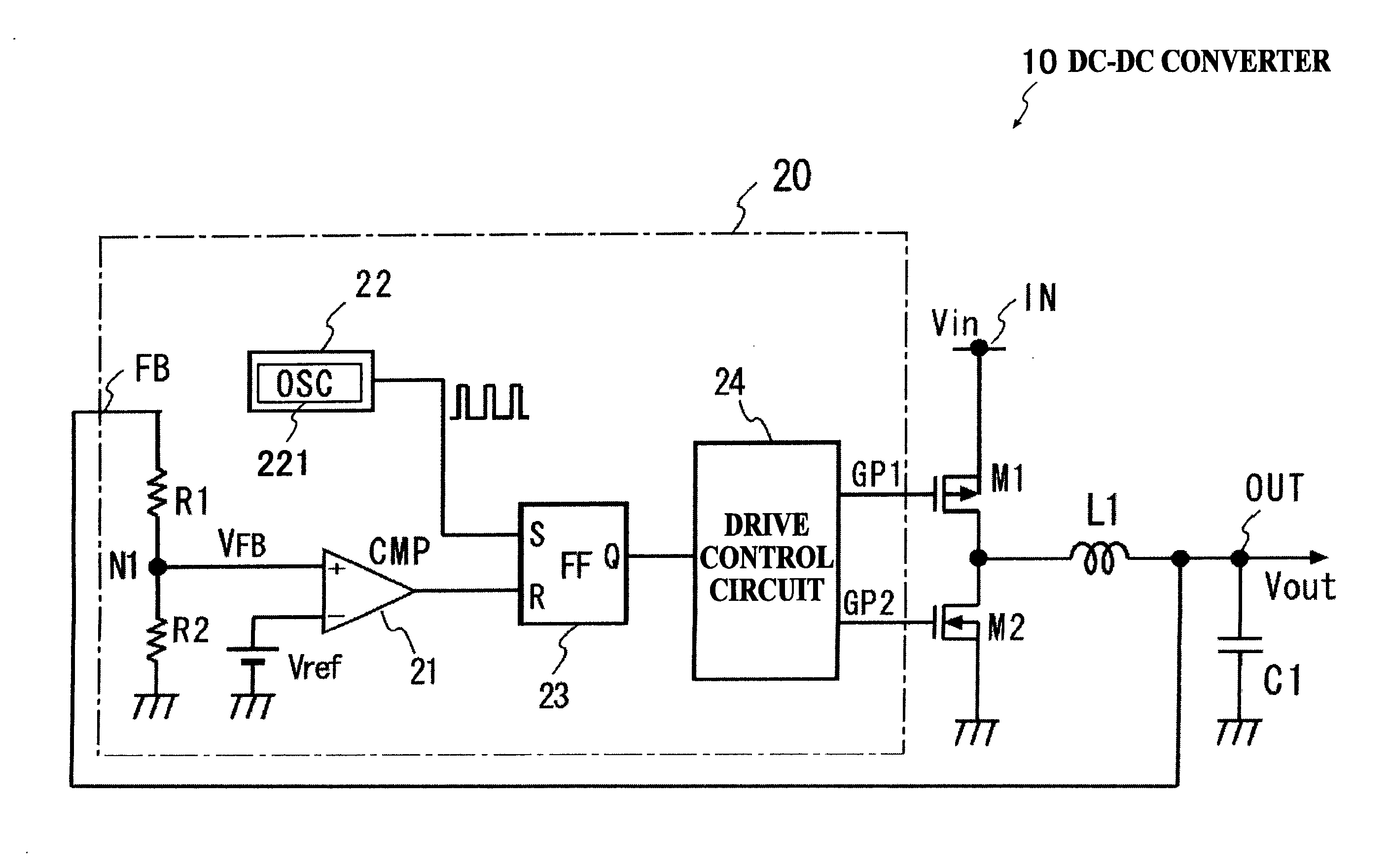
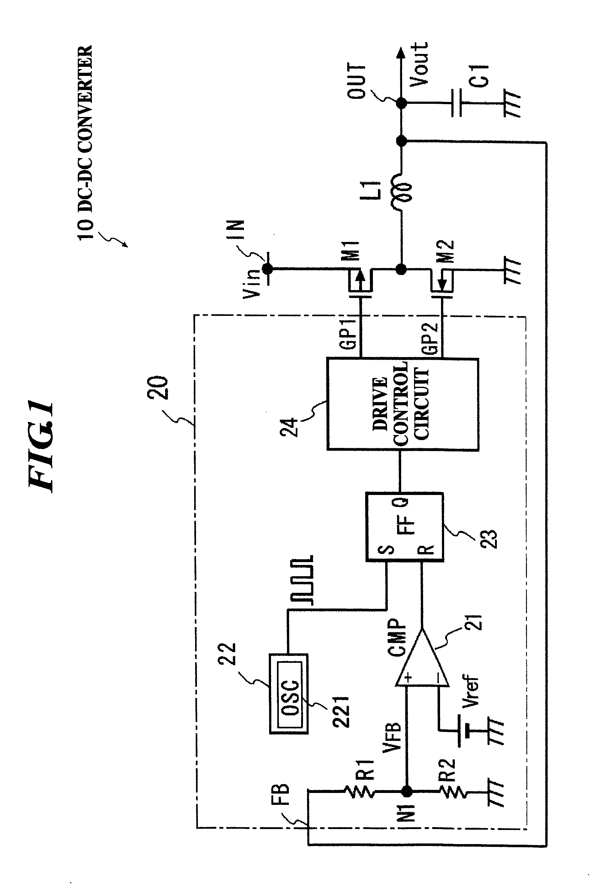
[0021]FIG. 1 shows an embodiment of a DC-DC converter of a switching regulator system with synchronous rectification in accordance with an embodiment of the present invention.

[0022]The DC-DC converter of the embodiment includes a coil L1 as an inductor; a switching transistor M1 for driving composed of a P channel MOSFET (metal-oxide-semiconductor field-effect transistor / insulated-gate field-effect transistor) and connected between a voltage input terminal IN, to which a DC input voltage Vin is applied, and one terminal of the coil L1, so as to flow a driving current into the coil L1; and a switching transistor M2 for rectification composed of an N channel MOSFET and connected between the one terminal of the coil L1 and a ground.

[0023]The DC-DC converter of the embodiment also includes a switching control circuit 20 to turn on and off the switching transistors M...


PUM


Abstract

A switching control circuit for controlling on/off of a switching element for driving an inductor for voltage conversion, the switching control circuit including: a voltage comparator for determining whether an output voltage of the inductor is in a first state where the output voltage is equal to or higher than a predetermined electric potential or in a second state where the output voltage is lower than the predetermined electric potential; a timing determination unit for determining an on-timing to turn on the switching element based on a clock signal having a predetermined frequency even when the output voltage is in the first state; and a drive control circuit for generating a driving signal to turn on or turn off the switching element based on an output signal of the timing determination unit.

Description

BACKGROUND OF THE INVENTION[0001]1. Field of the Invention[0002]The present invention relates to a DC-DC converter of a switching regulator system for converting a direct current (DC) voltage and a switching control circuit thereof, and in particular, relates to a technology effective to achieve a high-speed load response in the DC-DC converter.[0003]2. Description of the Related Art[0004]Currently, progress is made in development of a semiconductor integrated circuit (IC) such as a CPU for a low voltage and a large current. Accordingly, a load current often changes. Therefore as a characteristic of a DC-DC converter which supplies a DC source voltage to a system using the IC, a high-speed load response is required. As a power supply apparatus which supplies the DC source voltage to the system using the IC, a DC-DC converter of a switching regulator system is often used.[0005]As a conventional DC-DC converter of the switching regulator system, there is a DC-DC converter which contro...

Claims


Application Information

Patent Timeline
IPC IPC(8): G05F1/618
CPCH02M3/156
Inventor NAGAI, TOMIYUKITAKAHASHI, YOSHIHIRO
Owner MITSUMI ELECTRIC CO LTD
Why Eureka
Try Eureka