

Microcellular injection molding processes for personal and consumer care products and packaging
- Summary
- Abstract
- Description
- Claims
- Application Information
AI Technical Summary
Benefits of technology
Problems solved by technology
Method used
Image

Examples
example 1
Tensile Bar Molding Experiment
[0060]A standard LDPE resin was mixed together with a standard green LDPE-based batch formulation to produce a mixture containing 98.4% LDPE with the balance being inactive materials such as lubricants, slip agents, colorants, and dispersing agents. This resin formulation was used in all test specimen parts in this Example and was known as the LDPE resin mix. This resin was used in an injection molding trial to make the test specimen parts using the following experimental setup:
[0061]Injection molding machine, Arburg 320S Allrounder 55 ton (Arburg, Inc., Newington, Conn.)
[0062]Mold: ASTM D638 tensile test bar
[0063]Coolant temperature was 38 degrees C.
[0064]Super Critical Fluid injection unit from Trexel, Inc. (Woburn, Mass.)
[0065]Nitrogen was used as a supercritical fluid
[0066]Nitrogen injection flow rate was 0.05 kg / h (kilogram / hour) to 0.06 kg / h
[0067]Nitrogen dosage time was 1.5 seconds
[0068]Weight percentage of supercritical fluid was 0.15 to 0.17 we...
example 2
Tampon Applicator Barrel Experiment
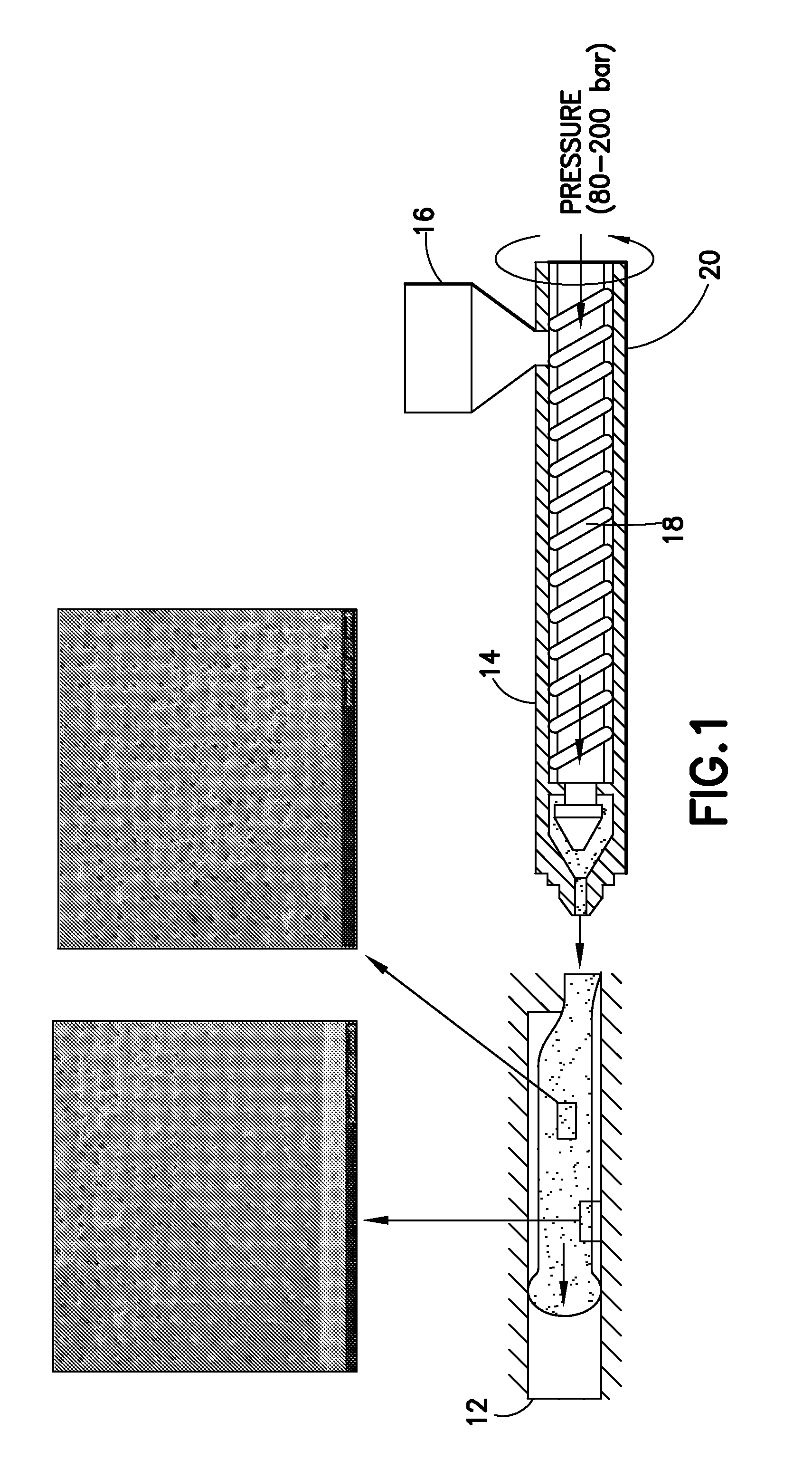
[0086]A four-cavity hot-runner mold exhibiting significant part complexity was mechanically and electrically linked both to the Arburg 320S injection molding system, including the feed and conveying systems, as shown in FIG. 1. A rounded, radiused nozzle was used to inject LDPE plastic. Electrical zone heating for the hot runner manifold was controlled by means of a temperature controller (available from Gammaflux Inc., Sterling, Va.). The mold was cooled using a chilled water system using inlet temperatures of either 10 or 22 degrees C. Other parameters were similar to those already described above for the tensile bar molding.
[0087]Some other molding parameters used in the tampon applicator molding include:
[0088]Core pull option set to activate prior to mold open and retracted prior to mold close
[0089]Air-actuated part ejection
[0090]Flow rates of 20-40 cubic centimeters per second
[0091]Barrel and molding temperatures of about 210 or 216 degrees C ...
example 3
Additional Tampon Applicator Barrel Experiments
[0116]The same four-cavity hot-runner mold described in Example 2 above was used to make some additional tampon applicator barrels. In this particular four-cavity mold, two of the cavities were the same ones used for Example 2. The tampon applicator barrels made with these two cavities resulted in barrels which correspond to a tampon having more absorbency than a regular, average, or more widely used tampon (a “super absorbent” tampon). The other two barrels were made with barrels that were more slender; that is, smaller diameter barrels that are typically used for the smaller, regular, or lower absorbency tampons. The mold is configured to allow either sets of these two cavities to be used, but not all four at once. Moreover, the two cavities used for the regular or lower absorbency tampon barrels were diamond polished to provide a very smooth, polished finish. The cavities for the barrels corresponding to the more absorbent tampons we...
PUM
| Property | Measurement | Unit |
|---|---|---|
| Fraction | aaaaa | aaaaa |
| Fraction | aaaaa | aaaaa |
| Time | aaaaa | aaaaa |
Abstract
Description
Claims
Application Information