Electron accelerator to generate a photon beam with an energy of more than 0.5 mev

a photon beam and accelerator technology, applied in the direction of x-ray tubes, nuclear targets, incadescent cooling arrangements, etc., can solve the problems of melting, failure of the entire apparatus, design that ensures a long-term, functionally capable bearing, etc., and achieve the effect of preventing thermal overloading of the targ

Inactive Publication Date: 2010-08-12
SIEMENS AG
View PDF22 Cites 14 Cited by
  • Summary
  • Abstract
  • Description
  • Claims
  • Application Information

AI Technical Summary

Benefits of technology

[0006]An object of the present invention is to toughen an electron accelerator...

Problems solved by technology

Medium beam powers in electron accelerators into the kilowatt range, beam diameters in the millimeter range and a lower degree of effectiveness in the transduction of the electron beam into the photon beam mean an extremely high local thermal loading of the target that can lead to its melting, and therefore to the failure of the entire apparatus.
A disadvantage of th...

Method used


Image

  • Electron accelerator to generate a photon beam with an energy of more than 0.5 mev
  • Electron accelerator to generate a photon beam with an energy of more than 0.5 mev
  • Electron accelerator to generate a photon beam with an energy of more than 0.5 mev

Examples


first embodiment

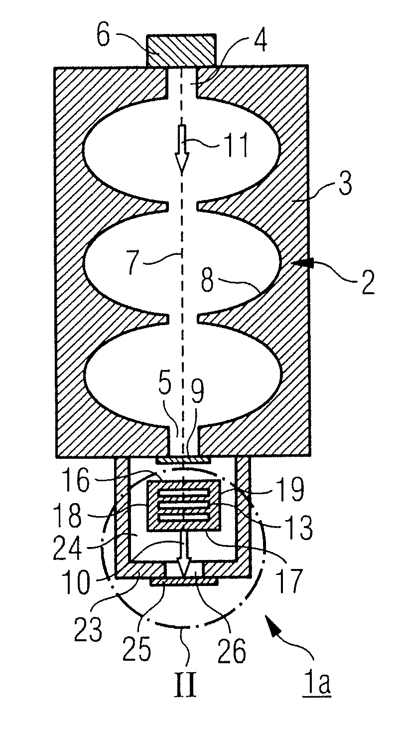
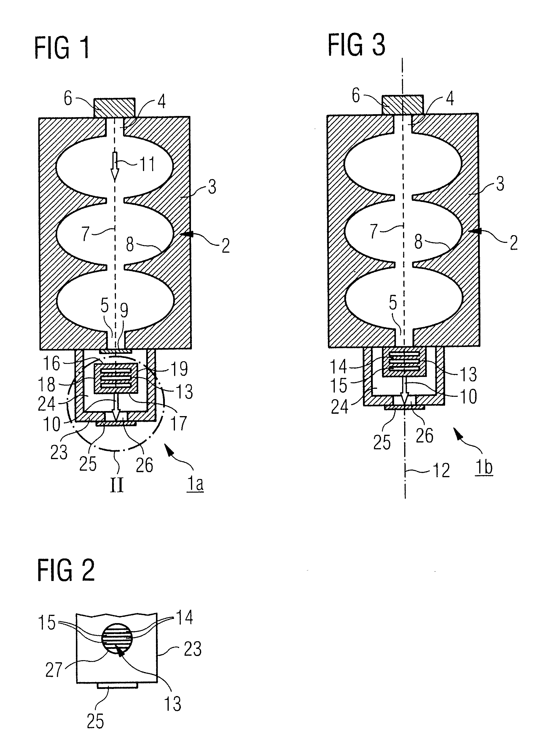
[0019]In the first embodiment variant of an electron accelerator 1a that is shown in FIGS. 1 through 3, the exit opening 5 is sealed in a vacuum-tight manner. In the case of FIG. 1, this ensues via a window 9 that is permeable to the electron beam 7, for example a window 9 consisting of titanium. A target 13 serving to convert the electron beam 7 into a Bremsstrahlung or into a photon beam 10 is positioned outside of the vacuum chamber and, due to the window 9, is not in fluid connection with the vacuum present in the vacuum chamber. The photon beam 10 emitted by the target 13 exhibits the same direction as the electron beam 7; both beams thus travel in the direction of a common beam axis 12 which penetrates the target 13. The target 13 (composed, for example, of tungsten, possibly with alloy additives) has multiple material layers 14 fashioned like lamellae. The material layers 14 are spaced (as viewed in the beam direction 11), wherein an approximately slit-shaped cooling channel ...

second embodiment

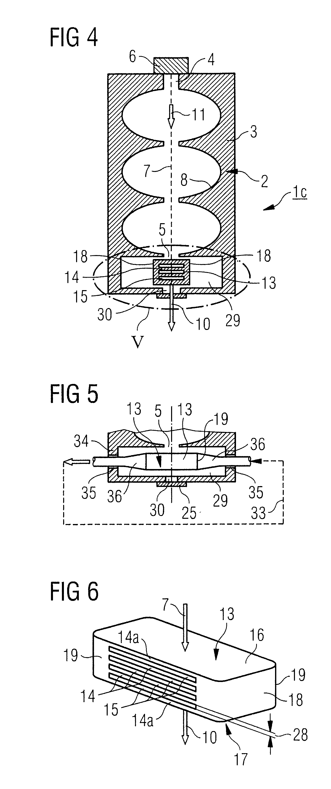
[0023]In the second embodiment variant of an electron accelerator 1c shown in FIG. 4, the target 13 is arranged in a space 29 surrounded by the housing 3 of the vacuum chamber 2. The space 29 is connected with the vacuum chamber 2 via the exit opening 5. The same vacuum as in the vacuum chamber 2 thus exists in the space 29. The space 29 does not necessarily need to be surrounded by the housing 3 of the vacuum chamber 2. Here it can also be a separate housing. In any case, a through-opening 30 is present in the wall that is sealed vacuum tight with an exit window 25 permeable to the photon beam 10. The space 29 is permeated vacuum-tight by a sub-segment of a coolant circuit 33. For this the housing wall 34 surrounding the space 29 is provided with through-openings 35 through which a tube conduit 36 is directed. The target 13 is respectively connected to the tube conduit 26 with its facing sides 19 into which the cooling channels 15 empty.


PUM


Abstract

An electron accelerator that generates a photon beam with an energy of more than 0.5 MeV by means of an electron beam charging a target has a vacuum chamber with an intake opening and an exit opening, and an electron source at the input side. The target is arranged outside the vacuum chamber in the region of the exit opening in a housing in which a window is present that is permeable to photons and that is arranged opposite the exit opening in the beam direction of the electron beam. The target is permeated by at least one cooling channel.

Description

BACKGROUND OF THE INVENTION[0001]1. Field of the Invention[0002]The present invention concerns an electron accelerator to generate a photon beam with an energy of more than 0.5 MeV, in particular for radiation therapy and for non-destructive materials testing.[0003]2. Description of the Prior Art[0004]In electron accelerators of the above type that are known from, for example, EP 0 872 872 A1 and EP 0 022 948, electrons emitted from an electron source are accelerated in a vacuum chamber, wherein they are directed onto a target upon leaving the vacuum chamber. Due to the high kinetic energy of the electrons, at least some electrons in the electron beam penetrate a layer of the target material. Photon radiation (Bremsstrahlung) with high energy in the MeV range arises due to the braking (deceleration) of the electrons in the target containing at least one element of higher atomic number (consisting of tungsten, for example). The arising photon beam exhibits the same direction as the e...

Claims


Application Information

Patent Timeline
IPC IPC(8): H01J7/26
CPCH01J2235/087H01J2235/1204H05H9/00H05G2/00H05H6/00H01J2235/1262H01J35/116
Inventor HEINKE, TOBIASMUELLER, SVENSETZER, STEFANWENDEROTH, MARKUS
Owner SIEMENS AG
Why Eureka
Try Eureka